


8
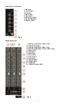
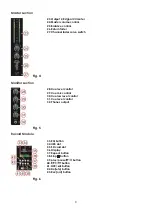
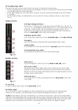
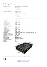
Master section
23. Output L/R signal VU meter
24. Master volume control
25. Balance control
26. Return fader
27. Channel fader curve switch
Fig. 4
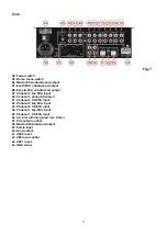
Monitor section
28. Cue level control
29. Cue mix control
30. Cue low level control
31. Cue level control
32. Phones output
Fig. 5
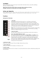
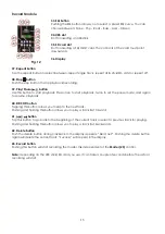
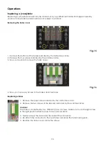
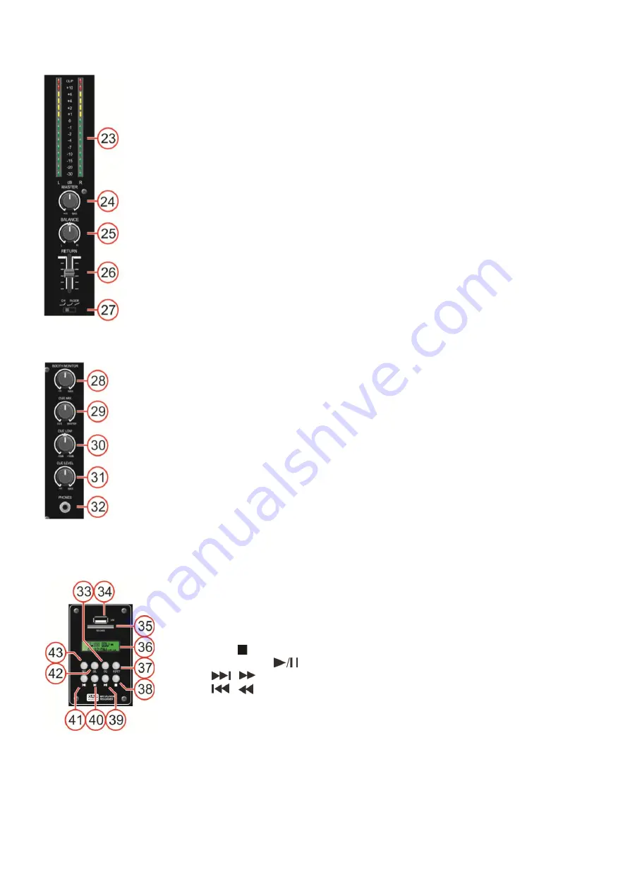
Record Module
33.
EQ button
34.
USB slot
35.
SD card slot
36.
Display
37. Repeat button
38. Stop button
39. play/pause button
40.
/
button
41. / button
42.
Del(ete) button
43.
Rec(ord) button
Fig. 6
Summary of Contents for Core Mix-3 USB
Page 22: ......


