background image


27 


EDGE EHS-1 

Product code: D1475B 
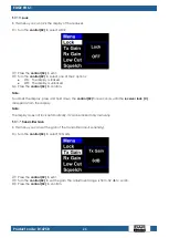
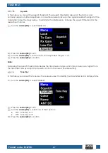
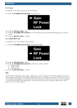
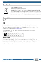
 

Squelch 

In this menu you can set the squelch threshold. The squelch threshold is pre-set at the factory and 
normally needs no further adjustment. In case the receiver picks up other signals besides the signal of the 
transmitter, follow the steps bellow. To eliminate the interference, increase the squelch threshold for the 
respective channel. 


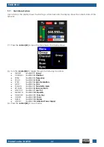
Turn the control (02) to select SQUELCH. 


Press the control (02) to edit. 


Turn the control (02) to set the value. The adjustment range is 1–10. 


Press the control (02) to confirm. 

Note: 

Increasing the squelch threshold decreases the transmission range, which may cause loss of signal from 
the transmitter. Always adjust the squelch control to the lowest possible setting. 
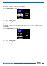
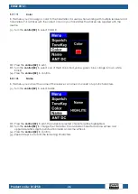
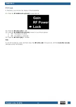
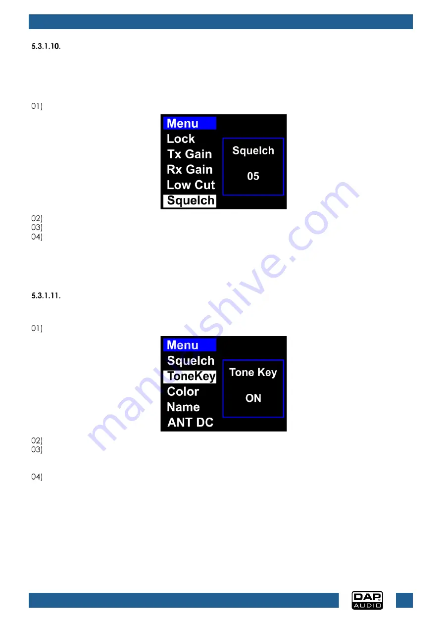
 

Tone Key 

In this menu you can set the tone key. The receiver uses it to identify the transmitter and its battery status. 


Turn the control (02) to select TONEKEY. 


Press the control (02) to edit. 


Turn the control (02) to select one of the 2 options: 


ON:  Tone key is on 


OFF:  Tone key is off 


Press the control (02) to confirm. 


Summary of Contents for EDGE EHS-1

Page 1: ...EDGE EHS 1 Highlite International B V Vestastraat 2 6468 EX Kerkrade the Netherlands Product code D1475B USER MANUAL ENGLISH V3...

Page 2: ...ce Non observance of the instructions in this user manual may result in serious injuries and damage of property 2023 DAP All rights reserved No part of this document may be copied published or otherwi...

Page 3: ...ns 13 Installation 13 Single Receiver 13 Two Receivers 14 Setup 15 Installation of the Antennas 15 Connecting to Power Supply 16 Power Linking of Multiple Devices 16 Setup Examples 17 4 x EDGE EHS 1 1...

Page 4: ...2 RF Output Power 32 Lock 33 Channel and Frequency Overview 34 6 Troubleshooting 35 Adjusting the Microphone Gain 35 7 Maintenance 36 Preventive Maintenance 36 Basic Cleaning Instructions 36 Correctiv...

Page 5: ...he device 4 x mounting screw for the 19 inch rack Fig 01 Intended Use This device is intended for use as a wireless microphone system It is suitable only for indoor installation Any other use not ment...

Page 6: ...h or serious injury CAUTION Indicates a potentially hazardous situation which if not avoided may result in minor or moderate injury Attention Indicates important information for the correct operation...

Page 7: ...red with the device Do not wrap the power cable around the power adapter or any other object This can damage the internal wires Do not cover the power adapter with anything when it is plugged into the...

Page 8: ...against harmful ingress of water Requirements for the User This product may be used by ordinary persons Maintenance and installation may be carried by ordinary persons Service shall be carried out on...

Page 9: ...e batteries not included Receiver Front View LCD display Control Menu Select Return button IR sensor Power button Fig 02 Receiver Back View Fig 03 Power cable safety eye Ground lift switch 3 pin XLR A...

Page 10: ...oduct code D1475B Microphone Handheld Transmitter Fig 04 Microphone head OLED display Power button on off Battery cover 20 DOWN button IR sensor Transmitter antenna Battery housing 2 x AA LR6 SET butt...

Page 11: ...ise ratio 100 dB RF antenna input impedance 50 Max balanced audio output 48 dBu Receiver output impedance 50 RF receiver antenna output voltage 15 V RF receiver antenna output current 150 mA Connectio...

Page 12: ...AA LR6 alkaline 1 5 V not included Average runtime 10 h Thermal Maximum ambient temperature ta 50 C Minimum ambient temperature 0 C Optional Accessories You can additionally purchase the following ac...

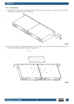
Page 13: ...12 EDGE EHS 1 Product code D1475B Dimensions Fig 05...

Page 14: ...a single or two receivers in a 19 inch rack To mount the receiver you need a Phillips screwdriver To mount the receiver in a two post rack follow the steps below Attach the mounting brackets and or t...

Page 15: ...ting brackets with the mounting screws to the receivers Use a Phillips screwdriver to tighten the mounting screws Fig 07 Attach the supplied mounting plate with the mounting screws to the bottom of bo...

Page 16: ...Installation of the Batteries on page 19 Switch on the transmitter See 4 3 7 Switching ON OFF Transmitter on page 20 Pair the transmitter with the receiver See 4 3 8 Pairing on page 20 Switch on the...

Page 17: ...not in use Power Linking of Multiple Devices This receiver supports power linking Power can be relayed to another receiver via the 12 15 V DC power connector OUT 13 Power linking of multiple devices m...

Page 18: ...with 4 receivers you can use a single antenna distributor and 1 set of unidirectional omnidirectional antennas The antennas receive the signal from the transmitter s and send it to the antenna distrib...

Page 19: ...necting the Receiver to Mixer Amplifier Attention Connect all data cables before supplying power Disconnect power supply before connecting or disconnecting data cables The receiver has a balanced 3 pi...

Page 20: ...from the socket outlet to disconnect the receiver from the power supply Installation of the Batteries The transmitter is delivered without batteries It accepts 2 x AA LR6 alkaline batteries To install...

Page 21: ...e transmitter and the receiver to the same channel and frequency follow the steps below Select a group on the receiver See 5 3 1 1 Group on page 23 Select a channel on the receiver See 5 3 1 2 Channel...

Page 22: ...ver and the transmitter See 4 3 5 Switching ON OFF Receiver on page 19 and 4 3 7 Switching ON OFF Transmitter on page 20 Control Panel Receiver A Antenna signal B AF signal mute C Receiver lock D Tran...

Page 23: ...the following 14 options GROUP See 5 3 1 1 Group CHANNEL See 5 3 1 2 Channel FREQ See 5 3 1 3 Frequency SCAN See 5 3 1 4 Scan SYNC See 5 3 1 5 Synchronization LOCK See 5 3 1 6 Lock TX GAIN See 5 3 1...

Page 24: ...this menu you can select a channel Each channel 1 14 has a unique fixed frequency See 5 5 Channel and Frequency Overview on page 34 Turn the control 02 to select CHANNEL Press the control 02 to edit...

Page 25: ...10 668 MHz This process may take up to 2 minutes Once the scan is finished you can see which frequencies are already in use and which are not Press the control 02 to return to the main menu Synchroniz...

Page 26: ...to confirm Note To unlock the display press and hold down the control 02 for 4 seconds until the receiver lock C disappears from the display Note The display does not lock automatically It can be lock...

Page 27: ...ut gain The adjustment range is from 32 dB to 4 dB Press the control 02 to confirm Low Cut In this menu you can set the low cut filter The low cut filter removes low frequency signals picked up by the...

Page 28: ...the control 02 to edit Turn the control 02 to set the value The adjustment range is 1 10 Press the control 02 to confirm Note Increasing the squelch threshold decreases the transmission range which ma...

Page 29: ...select one of the 8 colors red yellow green blue orange brown white black Press the control 02 to confirm Name In this menu you can set the name of the receiver A name can consist of up to 8 characte...

Page 30: ...select ON or OFF Press the control 02 to confirm Notes Select ON if the receiver is powered by the power adapter The active antenna will be powered via the 12 15 V DC BNC connectors 09 15 Select ON i...

Page 31: ...ute the transmitter with the power button 18 Press the power button 18 to mute the transmitter Press the power button 18 again to deactivate mute Main Menu Options Upon start up the display shows the...

Page 32: ...can select a channel Each channel 1 14 has a unique fixed frequency See 5 5 Channel and Frequency Overview on page 34 Press the UP DOWN buttons 25 20 to select CHANNEL Press the SET button 24 to edit...

Page 33: ...POWER Press the SET button 24 to edit Press the UP DOWN buttons 25 20 to select one of the 3 options LOW 10 mW MID 20 mW HIGH 30 mW Press the SET button 24 to confirm Note The maximum allowed RF outpu...

Page 34: ...select LOCK Press the SET button 24 to edit Press the UP DOWN buttons 25 20 to select one of the 2 options ON The display is locked OFF The display is unlocked Press the SET button 24 to confirm Note...

Page 35: ...525 MHz 13 654 850 MHz 13 655 100 MHz 13 655 350 MHz 13 655 600 MHz 13 655 850 MHz 14 665 700 MHz 14 665 950 MHz 14 666 200 MHz 14 666 450 MHz 14 666 700 MHz F G H I J CH Frequency CH Frequency CH Fre...

Page 36: ...oes not function correctly Make sure that the transmitter is switched on and the batteries are not depleted The transmitter is muted Make sure the transmitter is not muted The volume is too low Turn u...

Page 37: ...device to cool down for 5 minutes Clean the device with a soft lint free cloth Attention Do not immerse the device in liquid Do not use alcohol or solvents Corrective Maintenance The device does not c...

Page 38: ...ct code D1475B is in compliance with Directive 2014 53 EU RED Radio Equipment Directive The full text of the EU declaration of conformity is available at the respective product page on the website of...

Page 39: ...38 EDGE EHS 1 Product code D1475B...

Page 40: ...2023 DAP...

Reviews: