

9
GIG-164CFX
Order code: D2287
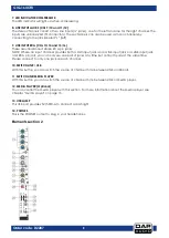
15. EQUALIZER
HI
The high-frequency range is processed with a shelving filter above 12 kHz. You can boost or cut the
bands up to 15 dB. In the center position (0 dB), the equalizer has a flat response.
MID
The mid control adjusts the mid frequency range. You can boost or cut the bands up to 15 dB. In the
center position (0 dB), the equalizer has a flat response.
MID FREQUENCE
The control can be used to change the mid frequency from 100Hz – 8Khz.
LOW
The low-frequency range is processed with a shelving filter below 80 Hz. You can boost or cut the bands
up to 15 dB. In the center position (0 dB), the equalizer has a flat response.
16. EQUALIZER BUTTON
Press this button to activate the channel equalizer.
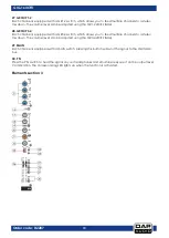
17. AUX 1
The AUX bus is used as additional, flexible send path for various applications. The AUX control adjusts the
volume level of the channel signal in the AUX 1 bus.
18. AUX 2
The AUX bus is used as additional, flexible send path for various applications. The AUX control adjusts the
volume level of the channel signal in the AUX 2 bus.
19. PRE/POST BUTTON
Press the PRE/POST switch to change the routing of the AUX path from “post-fader” to “pre-fader.” This
way the volume level of the effects signal is not affected by the channel fader.
20. AUX 3 (POST)
The AUX bus is used as additional, flexible send path for various applications. The AUX control adjusts the
volume level of the channel signal in the AUX 3 bus. This bus is post fader.
21. FX (POST)
The FX bus is used as a send path to the internal effect unit. The FX control adjusts the volume level of the
channel signal to the effects unit. This bus is post fader.
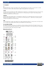
22. PAN CONTROL.
By using the panorama control you can change the input signal’s position within the stereo image. When
the panorama control is set to center position, the audio signal is equal for both the left and right output.
23. MUTE
The MUTE switch mutes the channel. This means that the channel signal has been removed from the main
mix and subgroups. At the same time the FX, monitor and AUX paths of the respective channel are
muted as well. The corresponding mute LED indicates that the channel has been muted.
24. CLIP
The CLIP LED lights up as soon as the channel's level is too high. In this case, reduce the channel's input
amplification with the gain control. The CLIP LED lights at a level of 3 dB below clipping.
25. SIGNAL LED
The signal indicator shows the presence of an audio signal at the output of the channel.
26. CHANNEL FADER
The channel fader adjusts the level of the channel signal as part of the main mix (or subgroup).
Summary of Contents for GIG-164CFX
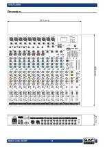
Page 22: ...21 GIG 164CFX Order code D2287 Dimensions...
Page 23: ...22 GIG 164CFX Order code D2287 Notes...
Page 24: ...2017 DAP Audio...