
4
GIG-164CFX
Order code: D2287
Operating Determinations
This system is not designed for permanent operation. Consistent operation breaks will ensure that the
system will serve you for a long time without defects.
If this system is operated in any other way, than the one described in this manual, the product may suffer
damages and the
warranty becomes void.
Any other operation may lead to dangers like short-circuit, burns, electric shock, etc.
You endanger your own safety and the safety of others!
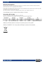
Connection with the mains
Connect the device to the mains with the power-plug.
Always pay attention, that the right color cable is connected to the right place.
International
EU Cable
UK Cable
US Cable
Pin
L
BROWN
RED
YELLOW/COPPER
PHASE
N
BLUE
BLACK
SILVER
NEUTRAL
YELLOW/GREEN
GREEN
GREEN
PROTECTIVE GROUND
Make sure that the device is always connected
properly
to the earth!
Improper installation can cause serious damage to people and property!
Summary of Contents for GIG-164CFX
Page 22: ...21 GIG 164CFX Order code D2287 Dimensions...
Page 23: ...22 GIG 164CFX Order code D2287 Notes...
Page 24: ...2017 DAP Audio...