background image


16 


GIG-164CFX 

Order code: D2287  

Installation 

Remove all packing materials from the DIG-164CFX. Check if all foam and plastic padding is removed. 
Secure the equipment into a 19" rack if preferred. Connect all cables.


Do not supply power before the whole system is set up and connected properly.


Always disconnect from electric mains power supply before cleaning or servicing. 
Damages caused by non-observance are not subject to warranty. 


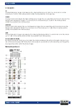
Set Up and Operation 

Before plugging the unit in, always make sure that the power supply matches the product specification 
voltage. Do not attempt to operate a 115V specification product on 230V power, or vice versa. 
 

Ready to start 

01)


Please check the available AC voltage in your country before connecting your mixer to the AC 
socket. 

02)


Be sure that the main power switch is turned off before connecting the mixer to the AC socket. You 
should also make sure that all input and output controls are turned down. This will avoid damage to 
your speakers and avoid excessive noise. 

03)


Always turn on the mixer before you turn on the power amplifier; turn off the mixer after the power 
amplifier is turned off. 

04)


Before connecting and disconnecting the unit from the power source, always turn off the unit. 


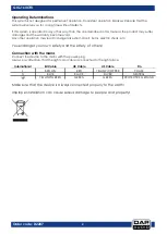
Set up and connection 

 
At this point you are in a position to successfully operate your GIG-164CFX Mixing Console. However, we 
advise you to carefully read the following section to be a real master of your own mixer. Not paying 
enough attention to the input signal level, to the routing of the signal and the assignment of the signal will 
result in unwanted distortion, a corrupted signal or no sound at all. So you should follow these procedures 
for every single channel: 


Before connecting mics or instruments, make sure that the power of all your system components, 
including the mixer, are turned off. Also, make sure that all the input and output controls are turned 
down. This will avoid damage to your speakers and avoid excessive noise. 


Properly connect all external devices such as mics, power amplifiers, speakers, effect processor, etc. 


First, turn on the power of any peripheral devices, then turn up the  power of the mixer. 


Set the output level of your mixer or the connected power amplifier at no more than 75%. 


Set the CONTROL ROOM/PHONE level at no more than 50%. 


Position HI, MID and LOW EQ controls on center position. 


Position panoramic (PAN/BAL) control on center position. 


While speaking into the mic (or playing the instrument), adjust the channel level control so that the 
CLIP LED will occasionally blink, in this way you will maintain good headroom and dynamic range. 


You can shape the tone of each channel by adjusting the equalizer controls as desired. 


Now repeat the same sequence for all the input channels. The main LEDs can move up into the red 
section, in this case you can adjust the overall output level through the MAIN MIX control. 


Summary of Contents for GIG-164CFX

Page 1: ...GIG 164CFX V1 Highlite International B V Vestastraat 2 6468 EX Kerkrade the Netherlands Order code D2287 MANUAL ENGLISH...

Page 2: ...device 6 Features 6 Overview 6 Control Elements 7 Elements section 1 7 Elements section 2 8 Elements section 3 10 Elements section 4 11 Backside 14 Media player Optional 15 Installation 16 Set Up and...

Page 3: ...our shipment includes GIG 164CFX mixing console 3 pin IEC power cable 1 5m User manual Safety Instructions Every person involved with the installation operation and maintenance of this system has to b...

Page 4: ...use DI boxes to balance unbalanced signals All incoming signals should be clear Make sure that the available voltage is not higher than stated on the rear panel Make sure that the power cord is never...

Page 5: ...ation may lead to dangers like short circuit burns electric shock etc You endanger your own safety and the safety of others Connection with the mains Connect the device to the mains with the power plu...

Page 6: ...mber 04 A brief description of the symptoms Claims The client has the obligation to check the delivered goods immediately upon delivery for any short comings and or visible defects or perform this che...

Page 7: ...and TRS Jack 2 Stereo Input Channels with RCA Jack 3 band EQ with sweepable MID and Clip LED on each MIC channel 4 band EQ and Clip LED on Stereo channels 4 AUX Send POST PRE per channel for monitorin...

Page 8: ...lts in level reduction 3 LOW CUT Press the LOW CUT switch to activate the high pass filter which blends out low frequency noise 100 Hz 18 dB octave This function can be used to cut the humming sound o...

Page 9: ...d a LINE input jack or a LINE input jack and RCA pin jack you can only use one pair of jacks at a time but not both pairs at the same time Please connect to only one jack on each channel 10 SWITCH LIN...

Page 10: ...e volume level of the effects signal is not affected by the channel fader 20 AUX 3 POST The AUX bus is used as additional flexible send path for various applications The AUX control adjusts the volume...

Page 11: ...GR3 4 switch which allows you to feed multiple channels to a stereo mix down The volume level can be adjusted using the GR3 4 LEVEL fader 29 MAIN Each channel is equipped with a MAIN switch pressing t...

Page 12: ...control adjusts the low mid frequency range This is a peak filter which boosts and cuts the frequencies centered at 500 Hz You can boost or cut the bands up to 15 dB When in center position 0 dB the e...

Page 13: ...peak LED flashes this means that the signal is too high near to the clipping of the effect input stage In this case reduce the level of the AUX 4 FX CHANNEL sends or AUX 4 FX MASTER 41 AUX1 AUX2 SEND...

Page 14: ...4 button the signal from GR 3 4 will be routed into the CONTROL ROOM output Press the button again the signal from GR 1 2 will be routed into the CONTROL ROOM output 56 PHONES With the PHONES control...

Page 15: ...N MIX signal 65 STEREO MAIN OUTPUT Unbalanced stereo jacks and provide the MAIN MIX signal 66 MAIN INSERT This is where you connect serial effects before the MAIN MIX fader control These serial effect...

Page 16: ...o fast forward or press this button to skip to the next track D RPT Press this button to repeat one track one folder or all tracks Repeat All Plays the complete content of the USB memory stick several...

Page 17: ...g Console However we advise you to carefully read the following section to be a real master of your own mixer Not paying enough attention to the input signal level to the routing of the signal and the...

Page 18: ...reliability Periodically check your cables A great number of problems faulty contacts ground hum discharges etc are caused entirely by using unsuitable or faulty cables Headphone Unbalanced Balanced F...

Page 19: ...e the illusion of more than one instrument from a single instrument sound Rate 0 92Hz 1 72Hz 50 59 Vocal Simulate a small space with slight decay time Rev decay time 0 8 0 9s Pre delay 0 45ms 60 69 Ro...

Page 20: ...specification label for details Troubleshooting DAP GIG 164CFX This troubleshooting guide is meant to help solve simple problems If a problem occurs carry out the steps below in sequence until a solu...

Page 21: ...e Chorus Vocal Rotary Small Room Flange Verb Large Hall Controls Mute switch Foot switching with LED indicator 100 position preset selector 10 preset 10 variation FOOT SW TIP FX SLEEVE GND Main mix se...

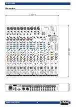
Page 22: ...21 GIG 164CFX Order code D2287 Dimensions...

Page 23: ...22 GIG 164CFX Order code D2287 Notes...

Page 24: ...2017 DAP Audio...

Reviews: