background image


40 


Ordercode: D2289  

GIG-202 Tab 

Digital In interface 


Note: 

This feature requires installing the input/output digital card (D2298), being the optional 

accessory belonging to the GIG-202 Tab. 


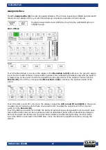
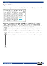
In order to access this page, press the Digital button (15) on the panel or touch the icon on the pages 

“Assign” or “System”. Then touch the Digital Input button. You can manage digital inputs only while 

operating in channels 1 to 20. There are two kinds of inputs to choose from: digital or analog. 


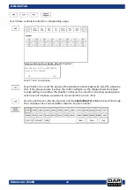
Touch this icon to change the input of a digital channel mode. The icon will show ON and 

it will light up red, indicating activation. If you go back to  Assign page, you can see that 

Digital button (15) on the panel is illuminated, indicating that the channel is assigned to a 

digital input. 


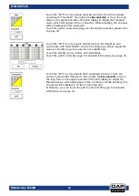
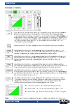
When a digital input channel is selected, you can adjust the input level by moving the 

fader which appears on the right-hand side of the screen or by turning the Encoder (36) 

on the panel. 


Summary of Contents for GIG-202 Tab

Page 1: ...GIG 202 Tab Highlite International B V Vestastraat 2 6468 EX Kerkrade the Netherlands Ordercode D2289 MANUAL V1 ENGLISH...

Page 2: ...Gate interface 33 Compressor interface 34 EQ Interface 35 Routing interface 36 FX1 2 interface 37 DCA set interface 39 Digital In interface 40 Digital Out interface 41 Save interface 42 Load interface...

Page 3: ...to be qualified follow the instructions of this manual Before you initial start up please make sure that there is no damage caused by transportation Should there be any consult your dealer and do not...

Page 4: ...and the power cord from time to time Please turn off the power switch when changing the power cord or signal cable or select the input mode switch Extreme frequency boosts in connection with a high in...

Page 5: ...and a brief description of the cause for the return Be sure to properly pack fixture any shipping damage resulting from inadequate packaging is the customer s responsibility Highlite reserves the rig...

Page 6: ...each output 20 analog inputs 8 inserts on first channels 10 analog outputs 100 mm precision motorized fader 4 x AUX sends pre post switchable per channel 4 x switchable AUX Subgroups 2 x 24 bit FX en...

Page 7: ...der is always automatically patched to the main parameter of your selected functionality This also gives the console the analogue feel to the digital environment The GIG 202 TAB features a 7 inch touc...

Page 8: ...t to properly set the level of the input gain to minimize noise and avoid overload distortion Channel select button There are 16 select mono channel buttons on the panel Press this button to route its...

Page 9: ...s the EQ frequency value Sub2 Aux6 master out control EQ Q level select Output control Sub2 Aux6 Sets the EQ Q level value Sub3 Aux7 master out control EQ Gain select Output control Sub 3 Aux7 Sets th...

Page 10: ...tton to see mixer page on the LCD screen where you can control all the input and output channel levels solo mute as well as rename the channel You can control DCA group level control see the figure be...

Page 11: ...sign select button Press this button to enter assign page Signal from a selected input channel can be assigned to Main AUX1 4 Sub1 4 or AUX5 8 and FX1 2 See the figure below For detailed information s...

Page 12: ...lows signals to pass through only when they are above a threshold setting Pressing the button twice will switch to the compressor settings The compressor reduces the level of an audio signal if its am...

Page 13: ...D2289 GIG 202 Tab EQ select button An equalizer is a filter that allows you to adjust the frequency level in the range of 20Hz 20KHz See the figure below For detailed information see page 35 Press onc...

Page 14: ...2289 GIG 202 Tab FX select button Press this button to show and edit the settings of internal effects Each FX owns 12 program effects See the figure below For detailed information see page 37 Press on...

Page 15: ...V select button Every microphone input is equipped with an individual phantom power which is controlled by the 48V phantom power button When you want to turn on phantom power of some channel the scree...

Page 16: ...annel of the pair Link DCA Apart from link the channels can also be grouped to DCA as stereo channel but without the possibility to channel the link in DCA On the contrary if the channel has been grou...

Page 17: ...n output level indicator Indicates the main level volume output Solo meter button When pressed the meter 18 will indicate the level of the selected solo channel s Solo clear button Clear all solo sele...

Page 18: ...DCA group Main Sub 1 4 assign buttons Assign outputs to selected channels and FX channels Subgroups and Auxiliaries can only be routed to main Motorized fader There is only one motorized fader to con...

Page 19: ...d to select the corresponding aux on the selected channel In Aux out mode button is not illuminated aux 1 4 5 8 28 can be used for selecting the auxiliary masters DCA set button Digital Controlled Amp...

Page 20: ...Bypass Press this button to mute the FX return channels Meters Press this button to get a total overview of all channels System Routing Press once to access the system menu Press again to access the r...

Page 21: ...of the selected channel TAP Enter button This button has two separate functions Enter Confirm the edited parameter values TAP In the FX menus the delay time can be tapped Ctrl room volume control Adju...

Page 22: ...me Solo button Press this button to send the signal of the selected channel s to the control room and headphone outputs Mute button When activated the selected channel s will be muted Pan button When...

Page 23: ...The INS ert connector stereo jack connector is used for connecting to external signal processors XLR Jack combo connector 9 16 Electronically balanced combo type input for connecting low impedance mic...

Page 24: ...e holder Before connecting the unit to the mains ensure that the voltage setting matches your local voltage Blown fuses should only be replaced with fuses of the same type and rating To disconnect the...

Page 25: ...uts are normally used as effect returns The inputs accept balanced stereo If a mono signal has to be returned to the mix connect it to the left input and then the right one as well as the left side wi...

Page 26: ...ity Pan Delay Link Output Assignment Input Channels 1 16 MAIN Subgroups 1 4 Aux sends 1 4 FX 1 2 Input Channels 17 20 X MAIN Subgroups 1 4 Aux sends 1 4 FX 1 2 Aux sends 1 4 FX sends 1 2 X MAIN Subgro...

Page 27: ...channel The icon will light up together with Solo 44 on the panel Touch this icon to mute the audio signal of the selected channel The icon will light up together with Mute 45 on the panel Press and...

Page 28: ...audio output level of the desired channel turn the Encoder 36 or touch the corresponding Main or Sub 1 4 26 controls on the right hand side of the panel Touch the AUX 1 4 and FX 1 2 icons on the disp...

Page 29: ...he selected audio channel Mute mutes the selected audio channel Press and hold the CH01 to rename the selected channel Move the fader to change the selected channel s audio output This fader s functio...

Page 30: ...o alter the phase by 180 If the phase reverse is active the button will light up The display shows the phase reverse setting in real time The Polarity control can be used for correcting audio signals...

Page 31: ...s to more advanced functions Touch the AUX5 8 SUB1 4 and FX1 2 to assign audio input to these channels or buses Rotate the Encoder 36 to adjust audio output level You can also use the Aux 5 8 controls...

Page 32: ...h delay for the selected channel ON OFF The icon will light up to indicate that the delay function has been enabled The delay time can be set up to 300ms at 48 kHz The parameters can be adjusted only...

Page 33: ...ill light up and synchronize with the ON OFF control on the EQ page Please adjust the values on the EQ page because it is not possible here Touch the Flat EQ icon to restore default settings Touch the...

Page 34: ...ust this control to set the amount of time after which the gate should change from close to open in a way similar to fade in function The adjustment range is between 0 5 and 200 ms Adjust this control...

Page 35: ...gain to reach the level that is determined by the ratio The adjustment range is between 10 and 150 milliseconds Adjust this control to set the compressor for the selected channel Release sets the amou...

Page 36: ...trol to separately set the central frequency of the equalizer s Low Low mid High mid High band The center frequency lies in the middle of the pass band between the lower and upper cutoff frequencies w...

Page 37: ...channels appearing on the display to Aux1 output On the Main routing page channel level cannot be adjusted You can adjust it in Sub Aux and FX pages is adjustable Adjust this control to route input c...

Page 38: ...FX1 2 as a preset by touching the Save button and following the instructions on the display Adjust the effect parameters by rotating the Adjust Parameter control or moving the fader on the right hand...

Page 39: ...ernately and quickly Feed Back Depth Mod Freq Efx Out Dry Out 07 Flanger Simulate to play with another person playing the same notes on the same instrument Feed Back Depth Mod Freq Efx Out Dry Out 08...

Page 40: ...can also access this function while on the menus Long Fader or Mixer Once you have edited the DCA group press the DCA Set button either on the panel 31 or on the display Repeat the above steps to edit...

Page 41: ...ly while operating in channels 1 to 20 There are two kinds of inputs to choose from digital or analog Touch this icon to change the input of a digital channel mode The icon will show ON and it will li...

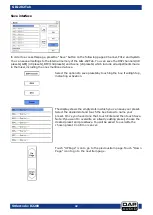
Page 42: ...20 AUX1 4 SUB 1 4 SOLO and main outputs can be used for converting digital outputs It is possible to select these digital outputs individually Touch this icon to change the output of a digital channel...

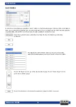
Page 43: ...es mentioned above Select the options to save presets by touching the box It will light up indicating activation The display shows the empty slots in which you can save your preset Select the desired...

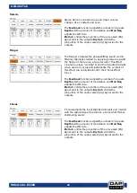
Page 44: ...GEQ effects DFX 1 2 or the scenes It is also possible to delete them all Select the options to save presets by touching the box It will light up indicating activation The display shows the slots in wh...

Page 45: ...nnel into which you would like to paste the copied settings The selected channel will light up red and the display will show ON You can select the channel either by using the display or by pressing th...

Page 46: ...pages functions If you touch the Default setting icon the factory setting will be restored The GIG 202 Tab is equipped with the safety lock function Follow the steps below to activate the function Tou...

Page 47: ...in the lower left corner Gain adjustment Once you have selected the desired frequency set gain by pressing the up down cursors on the panel or the arrows which appear on the screen It is also possible...

Page 48: ...beration is heard following the source signal Decay controls the amount of time it takes for the reverb to dissipate RoomSize controls the perceived size of the space being created by the reverb effec...

Page 49: ...s the proportion of the unprocessed dry signal sent to the outputs St Delay Stereo Delay provides control of left and right delay echo times When the delay time is tapped the ratio between the left an...

Page 50: ...ic when used on vocals and instruments The controls of this effect are nearly identical to the Chorus effect block The Feedback function adjusts the number of repeats Depth sets the amount of modulati...

Page 51: ...the processed reverb signal sent to the outputs Dry Out controls the proportion of the unprocessed dry signal sent to the outputs StDelay Rev Here we have combined Stereo Delay and Room reverb so tha...

Page 52: ...sed Efx signal sent to the outputs Dry Out controls the proportion of the unprocessed dry signal sent to the outputs Chorus Rev Here we have combined Chorus and Room reverb so that a single device can...

Page 53: ...channels assigned to the DCA group Assign channels to a DCA group on the GIG202 Tab 01 Press the DCA button 31 02 On the right side of the main display 47 select a DCA group 03 Select all the inputs...

Page 54: ...UX 4 SUB mode 01 Press the SYSTEM button 34 02 Touch the AUX SUB Mode button 03 04 Touch Yes to switch to 4AUX 4 SUB mode The GIG202 TAB is now configured with 4 Auxiliary send and 4 BUS send outputs...

Page 55: ...nalog mic preamps 01 Press the SYSTEM button 34 02 In the Scene part there are 3 options Load Copy Save Load a scene 01 Touch the load button 02 03 To select a previously saved preset touch the name o...

Page 56: ...A keyboard screen appears 06 Enter a name and confirm with Enter 07 Touch the save button 08 The preset is stored with the given name Remark If a preset already exists next screen will appear Touch Ye...

Page 57: ...Touch the copy button 02 03 Select the source channel by touching the Previous and Next Channel buttons 04 Select the destination channels by touching them 05 The status of the selected channels chang...

Page 58: ...to PFL the selected channel s If only the button 40 is pressed the master channel will be in PFL mode Default settings 01 Press the SYSTEM button 34 02 Touch the Default Setting button 03 04 Touch Yes...

Page 59: ...button 02 03 Touch the Select button 04 05 Touch Aux 1 Aux 2 Aux 3 Aux 4 FX1 or FX2 06 Touch Enter to confirm your choice 07 Switch to PRE by touching the PRE button Switch to POST by touching the POS...

Page 60: ...tput level of your mixer no more than 75 Set the CONTROL ROOM PHONE level no higher than to 50 Set HI HI MID LOW MID and LOW EQ controls to middle position Set panoramic PAN BAL control to center posi...

Page 61: ...reliability Periodically check your cables A great number of problems faulty contacts ground hum discharges etc are caused entirely by using unsuitable or faulty cables Headphone Unbalanced Balanced F...

Page 62: ...61 Ordercode D2289 GIG 202 Tab Block Diagram...

Page 63: ...put Level 21dBu SNR 107dBr EQ LowPass 20 6Hz 20kHz Frequency Range 20 6Hz 20kHz Gain 0dBu 24dB Q factor 0 4 24 HighPass 20Hz Gate Threshold Range 84dB 20dB Attack Time 0 5ms 200ms Release Time 5ms 100...

Page 64: ...2016 DAP Audio...
Reviews: