


8
3. Aux Sends
It is the same as for MONO Channels (see Mono Input Channel: 3. Aux Sends). Note that a mono sum is
taken from the stereo input.
4. Volume Control and Panning / Balancing
The only difference here to the Mono Channel described (see Mono Input Channel: 4. Fading and Panning)
is in the implementation of the Balance control (
13
). When a channel is run in stereo, this control determines
the relative balance of the Left and Right Channel signals being sent to the Left and Right Master Mix
busses. For example, with the Balance control turned fully clockwise, only the right portion of the channel’s
stereo signal will be added to the Master Mix.
If a Stereo Channel is run in mono (only the left input is connected), the Balance control acts as a pan in the
normal way.
MASTER SECTION
1. Aux Sends
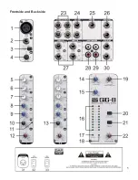
Aux Sends are provided on unbalanced 6.3mm jacks (
24
). Please adjust the input level control of your
effects unit to match the output level of your DAP Audio, this be can done when typical signals are run
through the Gig 8 and the Aux Sends are set to center (0dB). If your effects unit does not have an input gain
and the effects levels seems too low, remember that every channel Aux Send has up to 15 dB gain, which
should be more than enough to drive any effects unit.
2. Stereo Aux-returns
There are 2 additional stereo inputs (Aux Returns 1 and 2) on your Gig 8. Their level can be adjusted with
(
14
) and (
15
). Aux Returns 1.2 is permanently assigned to the Master Mix. If you connect a jack only to the
left socket, the Aux Return 1.2 operates in mono. This enables you to provide a wet cue mix (signal with
effect i.e. reverb) for the headphones or foldback speakers.
Note: Sometimes you want to narrow the stereo width of a reverb field. To do this you will have to come
back on 2 mono channels to get independent Pan for the left and right signals.
3. Metering
Master Mix level is displayed on a pair of accurate 10-segment peak meters (
16
). Two further LEDs indicate
Power on (
17
) and +48 V DC Phantom Power present (
18
).
The Master Mix meters should average around 0 dB during loud passages. If they read persistently higher,
or are peaking above +10 dB (top segment of the display) reduce either, the Master Mix volume and the
channel volume, or (as a last resort) channel input gain or instrument unit output level.
4. 2-Track (Tape / Rec) Input / Master Mix Output
Input
A 2-track input, on RCA phono jacks (
28
), provides easy connection to DAT and other professional and
semiprofessional audio equipment. The 2-track input is primarily for auditioning mix playback from tape.
Switch (
20
) “TAPE / REC TO CONTROL ROOM” routes the signal to the studio monitors. However, it can
also be routed to the Master Mix via switch (
21
) “TAPE / REC TO MASTER”. Here TAPE / REC TO
CONTROL ROOM (
20
) should be disengaged, or you will be listening to the 2-track signal twice!! With
button (
21
) depressed, you should have another stereo line input available to the mix.
Note: The 2-track input could be “normalled” to the output of a HIFI preamp, allowing you to monitor extra
sources such as vinyl, cassette, CD, etc.
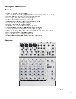
Summary of Contents for Gig 8
Page 1: ...Gig 8 ORDERCODE D2203...
Page 7: ...5 Frontside and Backside...
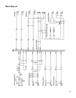
Page 16: ...14 Block Diagram...
Page 18: ...2004 DapAudio...


