


10
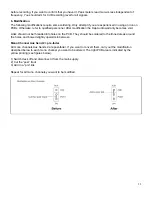
Experience tells us that the cables in a studio environment get tangled very quickly. A patch field will
facilitate patching and repatching considerably.
1. Desk Normalization
All board settings should be set to the normal default condition before or after every session. Usually
volumes are set to zero (minus infinity), EQ’s set flat and Aux Sends turned fully counter-clockwise, etc.
2. Selecting Inputs
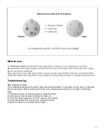
1) Mono Channels accept Mic or Line Inputs. If you are using the Mic input, make sure nothing is connected
to the Line input (and visa-versa).
Note: The Mic inputs are more sensitive than the Line inputs. Do not connect Mics with Phantom Power
switched on. Never use unbalanced Mic cables with the Phantom Power switched on ever! Shorting
the +48 V to earth can cause serious damage.
2) Stereo Channels accept any line level signals. Any stereo channel can be run in mono simply by
connecting into the left jack socket only. These channels are suitable for a variety of line-levels sources
including MIDI instruments and Tape returns from multi-track.
3) Stereo Aux Returns are primarily designed for returning effects units, though these too may be given over
to tape returns or MIDI instrument outputs.
3. Initializing Channels for Gain Setting
1) Set Gain to minimum and all Aux Sends to off (fully counter-clockwise).
2) Set EQ to flat (all knobs at 10 o’clock)
3) Where applicable, engage the Low Cut switch (
3
) for most Mics, except for signals with desired very low
frequency content.
4) Set the output level to unity Master (
22
set to”0”).
4. Auditioning a signal and setting up a channel
1) Turn up channel volume to unity gain (
12
set to”0”). All other channel volume controls should be set fully
counter-clockwise (minus infinity).
2) Generate a signal, i.e. a voice through a microphone. There should now be some activity at the peak
meters (
16
).
3) For Mic channels: Adjust the TRIM control (
4
) until transient peaks are regularly h6 dB. Continuous
signals should not exceed 0 dB.
4) For Stereo Channels and other stereo line inputs, use the output volume of the source instrument effect
gain adjustment, until transient peaks are regularly h 6db. Continuous signals should not exceed
0 dB.
5) Altering EQ will affect a channel’s gain. I f EQ is adjusted at any time, repeat steps 2, 3 or 4.
6) Turn the channel’s volume control fully counter-clockwise. Move onto next channel and repeat steps 1
thru 6.
7) Once all channel inputs have been set for level, turn all active channel level controls back to 0 dB. You
are now ready to start mixing.
5. Recording Levels
When recording to digital, it’s a good idea to keep the recorder’s peak meters below 0 dB. Most (not all esp.
Samplers) read 0 dB with some headroom left. This is because, unlike with analog, the onset of digital
distortion is as sudden as it is horrible. If you really want to take your recording level to the limit (and fully
exploit 16-bit digital’s 96 dB dynamic range for example), you’ll have to do some calibrating. How to
calibrate? You could run a tone at 0 dB from the mixer and use that as your DAT or ADAT reference. But
your DAT or ADAT may be way under its maximum input limit. Probably a better way to work out just how
hard you can drive your recorder is, to incrementally increase the record level until the onset of digital
distortion. Subtract 5 or 10 dB, and you never exceed that level. Engage “peak hold” on your recorder
Summary of Contents for Gig 8
Page 1: ...Gig 8 ORDERCODE D2203...
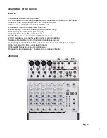
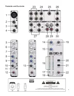
Page 7: ...5 Frontside and Backside...
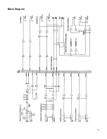
Page 16: ...14 Block Diagram...
Page 18: ...2004 DapAudio...