7
Set Up and Operation
Before plugging the unit in, always make sure that the power supply matches the product specification
voltage. Do not attempt to operate a 120V specification product on 230V power, or vice versa.
Mono Input Channel
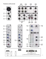
Each mono channel comes with a XLR Mic input (
1
) and a balanced Line input on 1/4” jack (
2
). Phantom
powering is switch able from the panel (
32
). The trim circuit has a wide range from +10dB to +60dB,
obviating the need for mic / line switching. The crucial operating input level +4 dBu and –10 dBV are clearly
and accurately marked (
4
).
1. Input Level Setting
Mic Channel input level is determined by the TRIM control (
4
). In addition to Master Mix metering, a channel
PEAK LED (
11
) illuminates, when a channel is going into overload. These LEDs take their cue from post-
EQ. This level sampling is particularly useful when using extreme EQ settings.
2. Equalizer
All mono input channels are fitted with 3-band EQ, plus a switch able Low Cut filter for eliminating unwanted
subsonics. The upper (
5
) and lower (
7
) shelving controls have their frequencies fixed at 12 Khz and 80 Hz
respectively. The Mid range control (
6
) has a peaking response, with Q fixed at 2 octaves, frequency at 2.5
Khz. All 3 bands have up to 15 dB of cut and boost, with a centre detent for “OFF”. The Low Cut filter (
3
),
slope at 18 dB/oct., -3 dB at 75 Hz, is ideally suited for reducing floor rumble, breathing noises and popping,
woolly bottom end, etc.
3. Aux Sends
Both Aux Sends
(8
&
9)
are mono and post-EQ. Aux Send 1 (
8
) is set pre-fader, while Aux Send 2 (
9
) is
post-fader.
Aux 2 can be made pre-fader on mono channels Aux 2, see “Modification” for more details.
4. Fading and Panning
GAIN to the Master Mix bus is ultimately determined by the Channel Volume control (
12
).
Channel Pan (
10
) positions the output of the channel in the stereo field. Its constant-power design ensures
there are no level discrepancies whether a signal is hard-panned, centre-stage or somewhere in between.
Such pinpoint accuracy will be a revelation, if you have been working on consoles with lower quality circuits.
STEREO INPUT CHANNEL
Each stereo channel comes with 2 balanced line level inputs on 1/4” TRS jacks (
27
), for left and right
signals. When only left input is connected, the channel operates in mono.
1. Input Gain Setting
The stereo Inputs are designed for any line level signal. Most line level sources such as MIDI instrument
and FX units will have their own output level control. Those that don’t, like CD-players, all have an output
level within the scope of the Gig 8. When the channel and master fader are set to unity gain the meters
should read between –4 dB and +7 dB. Remember that there is 15 dB Gain on both the channel as well as
the master fader.
2. Equalizer
There are no Low Cut filters on stereo channels, otherwise the EQ is in principle identical to that on MONO
channels (see Mono Input Channel: 2. Equalizer), except that the equalizer is stereo, of course!!
A stereo equalizer is generally preferable to using 2 mono equalizers when equalizing a stereo signal, as
often discrepancies between left and right settings occur.
Summary of Contents for Gig 8
Page 1: ...Gig 8 ORDERCODE D2203...
Page 7: ...5 Frontside and Backside...
Page 16: ...14 Block Diagram...
Page 18: ...2004 DapAudio...


