USB-DIO6400 Users Manual (Rev 1.1)
-
7-
http://www.daqsystem.com
3. Board Description
In this chapter, the primary functions of the USB3-DIO6400 board are described briefly. For more
information, refer to the device specification
3.1 Outside View
U
S
B
-
D
I
O
6
4
0
0
R
e
v
.
A
J7
JP7
J1
JP1
1
LED3
LED2
J6
U44
U46
U47
U45
U
1
3
Y1
D2
P1
U41
U40
U36
12.00
1
2
15
16
U35
SW3
J2
JP2
U27
L
E
D
1
JP4
J3
J4
J5
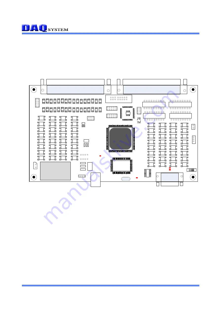
[Figure 3-1. USB-DIO6400 Layout]
There is a USB-B type connector at the bottom side to supply power and USB signals. It can be 32
channels Digital Input through 37PIN D-SUB (PLUG : J2) connector at the left top side. Also, it can
use 32 channels Digital Output through 37PIN D-SUB (SOCKET : J6) connector at the right top side.


