3 Description of Device and Operations
OM Hydraulic Aggregate, Version 1.0 01/2013
31
PE
Q1
PE
0
L1
N
PE
L1
T1
M
U1
U2
PE
L2
T2
14
24
1
2
3
3.3.3
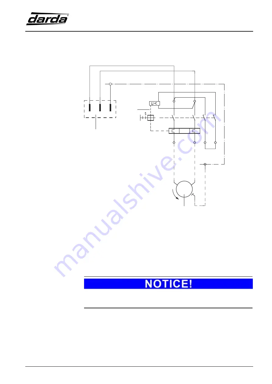
230 V circuit diagram
1
Wall-mounted device plug
2
Motor protection switch Q1
3
Engine/motor
Fig. 3-6
Circuit diagram
The electric connection takes the form of a (CEE17) device plug (316 / 6 h).
Please refer to the technical data for the mains voltage.
Connection and protective measures should follow VDE 0100 and the re-
quirements of the responsible energy supply company.


