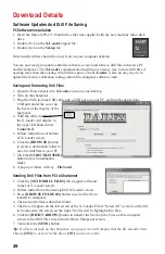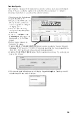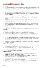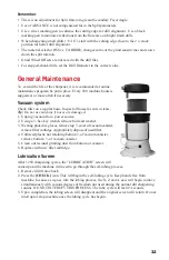
26
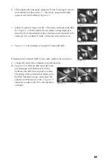
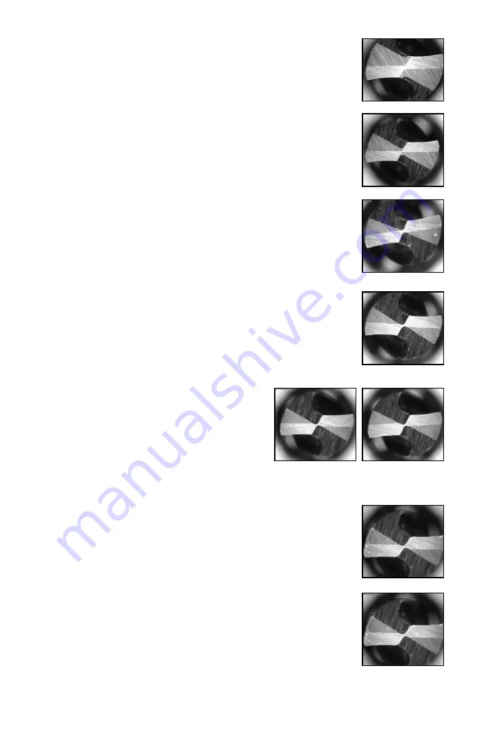
Figure F-2
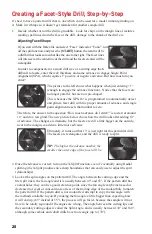
Figure F-3
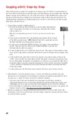
Figure F-4
4. Upon deciding what starting angles to use, enter them into the split
screen here. Back off the X and Z adjustments (in the “–” direction) in
the Split adjustment screen about .005” Grind the sample drill with the
initial split settings. It will look similar to
Figure F-2.
5. If the angles still look good, adjust the X and Z settings to remove
more material (Adjust in the “+” direction), and grind the drill again. It
will look similar to
Figure F-3
.
6. Adjust X and/or Z deeper (in the + direction), and look at the drill. See
Figure F-4
. In this photo, the secondary cutting edges produced by the
X adjustment are nice, but more material needs to be removed in Z, so
adjust Z in the + direction in the split screen.
10. Figure F-8
shows the grind after reducing the web thickness by 20%.
This is a pretty nice looking grind, if wanting a generic radial point,
this one is good to go.
11. Figure F-9
shows too much of a reduction in web thickness. The ra-
dius is beginning to creep into the primary cutting edge, and in another
10% would obliterate about half of it.
8. If creating a radially split drill, go ahead and change the split style to
Radius and grind the drill.
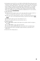
9. Figure F-6
is what the drill looks like after just
changing to the Radial split. If this is the desired
result, you’re done. If a more pronounced radius is
wanted, go to the web thickness screen and reduce
the entered web thickness by 10%.
Figure F-7
shows the results of the 10% web
thickness reduction. Note the roundness starting to
form up on the cutting edges of the secondary cutting lips.
Figure F-6
Figure F-7
Figure F-8
Figure F-9
7.
Figure F-5
shows remnant chisel edge. If the goal is to produce
an X-split drill, adding about 10° to the split angle to get rid of the
remnants of the facet heels, creating a good looking drill.
Figure F-5
Summary of Contents for XPS-16+
Page 1: ...Operating Instructions XPS 16 CNC Drill Grinder and Sharpener ...
Page 2: ......
Page 40: ...37 Notes ...
Page 41: ...38 ...


