background image

PVE400 USER’S GUIDE 


7.  Regulatory Information 


7.1  FCC Information 


This device complies with Part 15 of the FCC Rules. Operation is subject to the following conditions: 
This device may not cause harmful interference, and (2) this device must accept any interference received, 
including interference that may cause undesired operation. 


Federal Communication Commission (FCC) statement: 
This equipment has been tested and found to comply with the limits for a Class B digital device, pursuant to Part 
15 of the FCC Rules. These limits are designed to provide reasonable protection against harmful interference in 
a residential installation.  This equipment generates uses and can radiate radio frequency energy and, if not 
installed and used in accordance with the instructions, may cause harmful interference to radio communications.  
However, there is no guarantee that interference will not occur in a particular installation.  If this equipment does 
cause harmful interference to radio or television reception, which can be determined by turning the equipment 
off and on, the user is encouraged to try to correct the interference by one or more of the following measures: 


Reorient or relocate the receiving antenna. 


Increase the separation between the PV400 and receiver. 


Connect the equipment into an outlet on a circuit different from that to which the receiver is connected. 


Consult the supplier of PVE400 or an experienced radio/TV technician for help. 

 
Changes or modifications not expressly approved in writing by Darim Vision Co. may void the user's authority 
to operate this equipment. 


FCC ID: QTF-PVE400


Tested to Comply with FCC Standards 
FOR HOME OR OFFICE USE 


7.2  FCC RF Radiation Exposure Statement 


In August 1996, the Federal Communications Commission (FCC) of the US adopted an updated safety standard 
for human exposure to radio frequency electromagnetic energy emitted by FCC regulated transmitters. The 
design of PVE400 complies with the FCC guidelines and those standards. 
 
To maintain compliance with FCC RF exposure guidelines, if you wear device on your body, use the supplied or 
approved carrying case, holster, or other body-worn accessory.  If you do not use a body-worn accessory, ensure 
the antenna is at least 1.5 cm from your body when transmitting.  Use of non-approved accessories may violate 
FCC RF exposure guidelines. 

Copyright © 2007-2008 Darim Vision Co, All Rights Reserved


- 26 - 

Summary of Contents for VIDEOSPIDER PVE400 edition

Page 1: ...User s Guide Rev 1 3a May 30 2008 Copyright 2007 2008 Darim Vision Co All Rights Reserved...

Page 2: ...m Vision Co All Rights Reserved No part of this reference manual may be reproduced or transmitted in any form or by any means without the prior written permission of this company Throughout this manua...

Page 3: ...red connection configuration 12 3 2 2 Wireless connection configuration 14 3 3 VIDEO AND AUDIO CONFIGURATION 16 3 4 VIEWING VIDEO 17 3 5 MONITORING THE BATTERY STATUS 19 3 6 UPGRADING FIRMWARE 20 3 7...

Page 4: ...either an Incident Response Command Post or from a Central Operations Control Centre delivering real time video and audio information from outdoor environments back to a centrally managed control loc...

Page 5: ...output for camera power feed Up to 4 hours operating time on single Field replaceable battery Multi device Enterprise management from Darim s VideoSpider Console 1 2 Requirements The following are th...

Page 6: ...PVE400 USER S GUIDE 2 INSTALLATION STEPS This chapter describes the installation procedure of the PVE400 accessories Figure 2 PVE400 interface Copyright 2007 2008 Darim Vision Co All Rights Reserved 6...

Page 7: ...2 Installing the camera PVE400 is bundled with 1 3 Sony Ex View HAD CCD Hi res weatherproof bullet camera The camera comes with Fischer Automatic Latching Self Aligned 5 pin connector Gently plug and...

Page 8: ...rce 2 5 Battery charging The battery can be charged using an external charger optionally supplied p n PVE ECx or internally using bundled AC 12VDC power adapter PVE PS with AUX adapter The charging ti...

Page 9: ...this device may present a risk of fire or chemical burn hazard if mistreated Do not recharge disassemble heat above 60 C 140 F or incinerate Replace battery with Saft model 1S1P MP 176065 only Use of...

Page 10: ...e factory default configuration for Ethernet IP 192 168 1 250 static To access PVE400 for the first time using the wired connection PC must be on the same network subnet The network settings can be ch...

Page 11: ...he internal time clock can be adjusted to reference time server using the standard NTP protocol during boot time Most of Linux systems have NTP Daemon to synchronize time between machines The best opt...

Page 12: ...be automatically set accordingly to the connection The Ethernet IP mode drop down list allows you to select the IP configurations parameters DHCP Server PVE400 has an internal DHCP server and can pro...

Page 13: ...on the Network configuration page Disabled Ethernet adapter is turned off The Ethernet MAC address parameter is a read only one and shows unique MAC address of Ethernet adapter PVE400 All PVE400 devic...

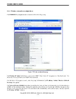
Page 14: ...the Static IP Assignment mode enter the proper information for IP address Subnet Mask and Default Gateway if required The Network Name ESSID filed allows specifying the Network Name or Extended Servi...

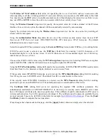
Page 15: ...on Access Point Choose either TKIP or AES value using the WPA Encryption drop down list Selecting TKIP sets encryption cipher for WPA PSK while the AES selection sets encryption cipher for WPA2 PSK U...

Page 16: ...y but it will not exceed the specified value in this field The Video Encoder Target Rate parameter field serves for specifying maximum allowed bit rate for video compression It depends on the link qua...

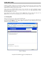
Page 17: ...Frame Rate and Video Encoder Target Rate selection fields If any changes have been made on this page click the Apply button otherwise simply select other tab The Restart button will restart the stream...

Page 18: ...ption is using Darim s Video Spider software it can be purchased separately The Video Spider software will allow to monitor and record data from multiple PVE400 units The Video Spider software has Cli...

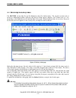
Page 19: ...maximum The device will normally operate until the battery is discharged down to 3 0V and then shutdown The rechargeable Lithium Ion battery rated with capacity 6 8Ah if discharged till 2 5V It means...

Page 20: ...r off on cycle is recommended after the upgrade procedure If the status after the upgrade reports an error check the network connection to upgrade site if it can be accessed from the network segment o...

Page 21: ...o stream LED will start blinking Yellow LED will start blinking if quality of connection degraded Red LED will start blinking if battery capacity below 10 and will be solid red when less than 5 remain...

Page 22: ...s added to the list all other devices are automatically prevented from accessing with the exception of those devices from the list To add a new trusted address click the Add button Using the Delete bu...

Page 23: ...gateway for them Example Ext device 1 PVE400 Ethernet side PVE400 Wireless side IP 192 168 1 2 IP 192 168 1 250 IP 172 31 1 200 MASK 255 255 255 0 MASK 255 255 255 0 MASK 255 255 0 0 GW 192 168 1 250...

Page 24: ...ential RMA information The nearest Darim s Regional Representative can be found at http www darimcctv com support pve_rep php Or send an e mail to usasales darim com The Regional Representative will b...

Page 25: ...manual failure of the end user to follow the maintenance procedures in the service manual for the Product where a schedule is specified for regular replacement or maintenance or cleaning of certain pa...

Page 26: ...correct the interference by one or more of the following measures Reorient or relocate the receiving antenna Increase the separation between the PV400 and receiver Connect the equipment into an outle...

Page 27: ...bel The alert symbol indicates that PVE400 is not certified to operate in France Outdoor use in France is restricted to 10mW EIRP for band 2454 2483 5 MHz Note CE mark is not applicable if WMC7300 is...

Page 28: ...pplicable in the European Union member states The WEEE marking on this product indicates that the product must not be disposed of together with household waste To prevent possible harm to human health...

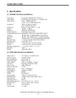
Page 29: ...ition External power 10 16V DC 1 5A Dimensions 5 3 x4 45 x1 46 134x113x37mm Weight 1 65lb 0 75kG without caring case Operating temperature 4 F 104 F 20 C 40 C Humidity 0 95 Rating NEMA 4R IP66 8 2 PVE...

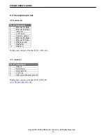
Page 30: ...hernet Rx Data 7 Ethernet Tx Data 8 RS232 ground 9 RS232 Rx 10 RS232 Tx Mating male connector Fischer S1031 A010 140 A V connector Pin Designation 1 Video in 2 Audio input 3 Audio ground 4 12V out 5 V...

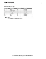
Page 31: ...green 6 Ethernet 2 white orange 1 Ethernet 5 white brown 7 reserved 6 white green 3 Ethernet 7 orange 2 Ethernet 8 white blue 5 RS232 common 9 brown 8 RS232 Rx 10 blue 4 RS232 Tx Note Ethernet wired...

Page 32: ...y PVE RPC US US type Power cord for PVE PS PVE RPC EUR European type Power cord for PVE PS PVE RPC UK UK type Power cord for PVE PS PVE RPC AUS Australian type Power cord for PVE PS PVE VPS Vehicle DC...

Reviews: