You have compeleted assembling your Emblaser Core.
Your next step is to work through the User Manual. Go to this link to get started:
darklylabs.com/e2start
CONGRATULATIONS!
Unit 3, 99-101 Western Ave, Westmeadows, 3049 Australia
info@darklylabs.com
●
www.darklylabs.com
Copyright © Darkly Digital Pty Ltd (Darkly Labs) 2014-2019.
If you need more inforamtion about the assembly or operation of your Emblaser Core,
check the Help Centre:
darklylabs.com/help
Otherwise, please email us at:
support@darklylabs.com
Technical support
Darkly Labs
R
77
Summary of Contents for Emblaser Core
Page 1: ...Emblaser Core Assembly Manual Rev 1 32 User Assembly Manual English Darkly LabsR Kit Rev 1 0 ...
Page 13: ...Step 1 04 Place the 4x Cable Management Clips in the recesses on the Rear Panel 13 ...
Page 21: ...21 Step 2 06 Assemble the four Idle Pulleys ...
Page 33: ...33 33 Step 2 16 Route the Belt around the two Lower Position Idle Pulleys as shown ...
Page 35: ...35 35 Step 2 18 Route the Belt behind lower position pulley in the Gantry Carriage ...
Page 41: ...41 41 Step 2 22 Route the Belt around the two Upper Position Idle Pulleys as shown ...
Page 42: ...42 42 Step 2 23 Pass the Belt through the Gantry Carraige and around the Motor Pulley ...
Page 43: ...43 43 Step 2 24 Route the Belt behind lower position pulley in the Gantry Carriage ...
Page 52: ...Fold the Driver Board Cover as shown in the diagram Step 3 07 52 52 ...
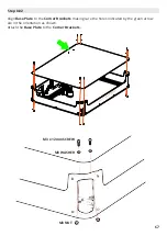
Page 68: ...Attach the Rubber Feet to the Base Plate as shown below Step 8 03 68 68 ...
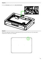
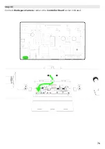
Page 76: ...Connect Workspace Camera cable to the Controller Board socket indicated Step 03 76 76 ...

