UNIT OVERVIEW
2
3
4
5
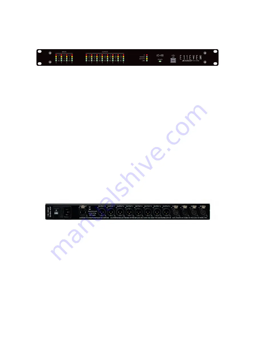
Front Panel
1
2
3
4
8
1
1.
Input Meters:
Real time LED input meters show level from maximum input level (clip) in 4-segments... Signal present,
6dB below clipping, 0dB/maximum input level and clip*.
*If analogue input clipping is neared by 1dB, the red input Clip LED will illuminate to show this.
2.
Output Meters:
Real time LED output meters show level from the limiter threshold in 4-segments... Signal present, 6dB
below limiter threshold, Limiter threshold and 3dB into limiting. Note: The red l3 LED will also
illuminate if this output is muted.
3.
Comms:
ID: Flashes when the ‘ID’ button is clicked on a connected device within the D-Net software. Master: [for
future use] Activity: Flashes when communication is taking place between the device and D-Net
software. Link: Illuminates when a suitable Ethernet connection is established.
4.
Power Light:
Illuminates when a suitable power source is connected and the unit is powered on.
5.
USB port:
USB type B port for single unit connection to a computer running the D-Net software.
Rear Panel
1.
Main Power Inlet, Fuse and Power Switch:
3-pin IEC input, fused [5mm x 20mm, 3.15A, 250V, Anti-Surge (T)], 90-250VAC, 50-60Hz <40W.
A spare fuse is located within the fuse holder – only replace with the correctly rated fuse!
2.
Ethernet Computer Control Port:
Neutrik etherCON RJ45 network Ethernet port accepts either a standard CAT5 cable or housed RJ45
connector for connection to a computer (or suitable network switch to control multiple units
simultaneously).
3.
Balanced Analogue Audio Outputs:
The analogue outputs are wired as follows: Pin 1: Shield/Ground Pin 2: Signal Hot (+) Pin 3: Signal Cold (-)
4.
Balanced Analogue Audio Inputs:
The analogue inputs are wired as follows: Pin 1: Shield/Ground Pin 2: Signal Hot (+) Pin 3: Signal Cold (-)
E11EVEN SOUND \ iO-48 \ User’s Manual
Summary of Contents for E11EVEN 11SOUND
Page 29: ...www 11sound com ...


