Manual del Usuario
/ DASnet Rack 99 230V ETH /
User’s Manual
Basic connection of
DASnet Matrix 99 ethernet
There is a termination resistor which can be activated with a switch. It is recommendable to
engage it in the first and last matrix of the network to increase network stability.
With this system, ideal solution for touring, we can link a maximum number of 288 devices,
with a length of the DASnet data cable should higher than 1000 meters (counting both XLR
data cables and ecp_xx), through multiple
DASnet Matrix 99 ethernet
units and converting the
data transmission from ethernet to fiber optic. Note: always CAT5 cables for ethernet as a
minimum.
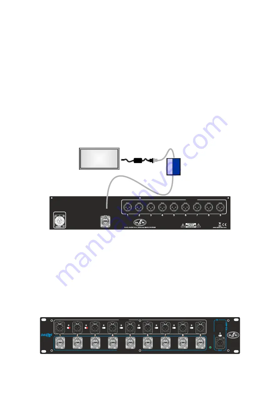
DASnet Matrix 99 ethernet
needs a USB to RS-485 converter and a MOXA Nport 5150
converter, to convert data from RS-485 to ethernet. These converters can be provided by DAS
Audio. The converters have to be connected to the
DASnet Matrix 99 ethernet
using the
ETHERNET INPUT connector, on the rear panel.
AUDIO IN
AUDIO / DASNET OUT
LINK 1&2
LINK 2&3
LINK 3&4
LINK 4&5
LINK 5&6
LINK 6&7
LINK 7&8
LINK 8&9
TERMINATION
RESISTOR
Matrix 9X9
POWER
ON
ON
2
3
1
PUSH
2
3
1
PUSH
2
3
1
PUSH
2
3
1
PUSH
2
3
1
PUSH
2
3
1
PUSH
2
3
1
PUSH
2
3
1
PUSH
2
3
1
PUSH
1
3
2
POWER
ON
8
DASnet
Net 1
USB-RS485
MOXA
Nport 5150
1
3
2
1
3
2
1
3
2
1
3
2
1
3
2
1
3
2
1
3
2
1
3
2
1
3
2
AUDIO OUT
100-230V~ 50/60Hz
10W
AC INPUT
ETHERNET
INPUT
Internally, each
DASnet Matrix 99 ethernet
has an RS-485 repeater that is directly connected
after the RS-485 input. The repeater allows having larger distances of cabling in the network
and a much higher number of devices without loosing capabilities.
The
Dasnet Matrix 99 ethernet
is an ideal solution for audio and monitoring data distribution in
self powered cabinets that include
DASnet
:
aero 20A
,
aero 40A
,
UX-221A
,
UX-30A
,
UX-218A
,
UX-
218RA
,
LX-218CA.net
,
Road-12A.net
,
Road-15A.net
, etc.
Example of input links
On the front panel, the
DASnet Matrix 99 ethernet
offers flexible routing with switches that
allow you to mount an audio input to several outputs. The nine audio inputs can be linked
directly to their corresponding ethercon outputs. In addition, a single audio input can be linked
to all ethercon outputs by using the switches.
That is, if you look at the figure below, we have linked the inputs 1 with 2 on one side and 2
with 3 on the other. With this, it is enough to enter audio through connector 1 to output that
signal through all the connected output connectors: 1, 2 and 3, both ethercon on the front,
and XLR on the rear.
With this system, we can send a signal to all the equipment (linking all the outputs with the
input 1) or create several zones with different signal sends.


