background image


Cardioid Preset


This unique feature facilitates the configuration 

of two or three units to create a cardioid response 
pattern. This is useful in situations where on-stage 
bass level projected from the subs needs to be 
kept to a minimum. 
 

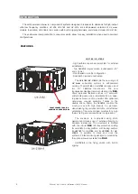
To  set-up  a  cardioid  configuration  with  two 

stacked units, place the bottom unit facing the 
audience and the top box facing the stage. Set the 
controls  for  level,  polarity  and  cut-off  frequency 
identically  on  both  units.  Daisy-chain  the  signal 
from one unit to the other (do not activate the 
satellite  output  high-pass  filter).  Activate  the 
Cardioid  Preset  button  on  the  box  facing  the 
stage.  This  provides  the  level  and  phase 
adjustments  necessary  to  cancel  the  rear 
projected  sound  waves  “cleaning”  the  stage  of 
unwanted bass.
 

To assemble a cardioid configuration with three 

stacked units, the procedure is basically the same. 
Place  the  lower  and  top  boxes  facing  the 
audience, the middle box facing the stage. Daisy-
chain the signal, make sure the level, polarity and 
cut-off frequency are the same on all the boxes 
and lastly, activate the Cardioid Preset button on 
the box facing the stage.


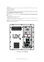
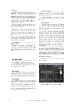
In the next figure, we can view this menu of the 

UX-221A

 units.

14

Manual del Usuario

 / UX series / 

User’s Manual


ON / OFF


A  sound  system  should  be  switched  on 

sequentially. Switch on the self-powered units last 
in your sound system (switch on the subwoofer 
before the mid-high system). Switch on the sound 
sources such as CD players or turntables, then the 
mixer,  then the  processors, and  finally the  self-
powered  unit.  If  you  have  several  units,  it  is 
recommended  that  you  switch  them  on 
sequentially one at a time.
 

Follow the inverse order when switching off, 

turning  self-powered  units  off  before  any  other 
element in the sound system.


Disconnect the device by removing the mains 

connector  from  the  mains  socket.  The  mains 
connector and mains socket must always be freely 
accessible and never covered or blocked in any 
way. 
 

The models use a power cable equipped with 

a Neutrik PowerCon TRUE1 connector. Power can 
be daisy chained via the TRUE1 output connector 
(see details on product label).


IMPORTANT

:  Do  not  disconnect  the  unit 

while in use.
 

Ensure that the device is disconnected from 

the mains by observing that the ON LED is turned 
off. Please note that the ON LED can stay on for 
several seconds after the mains power has been 
disconnected.


Overheating


This  equipment  does  not  normally  overheat 

during normal conditions of use. When overheating 
occurs, the unit protects itself. You should then 
find  out  why  and  if  necessary  contact  an 
authorised dealer for technical assistance.
 

Normally it is enough just to let the unit cool 

down after you have corrected the problem so that 
the system functions properly again.


Equalisation


The unit does not need extreme settings of 

equalisation to produce quality sound. Avoid high 
levels of gain on the equalisers. Gain values above 
+3 dB on a console’s EQ are not recommended.


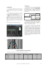
Overload indicator


This device has a SIGNAL/LIMIT indicator. The 

red light indicates the signal is excessive.
 

The  indicator should  not  be  lit  continuously. 

This distorts the signal (quickly fatiguing your ears) 
and may damage the speakers.


Low mains voltage


If  mains  voltage  falls  below  the  shutdown 

voltage  for  the  unit,  it  will  stop  playing.  When 
acceptable levels are regained, the unit will switch 
back on automatically.
 

The  unit  recognised  the  value  of  mains 

automatically. The unit works from 80V to 260V 
(both rms).

View of 

 with the cardioid presets

TM

DASnet

Summary of Contents for UX Series

Page 1: ...tes de utilizar el equipo lea la secci n Precauciones de seguridad de este manual Conserveestemanualparafuturasconsultas Before operating the device please read the Safety precautions section of this...

Page 2: ...NE DRAWINGS 3 4 5 11 10 17 29 31 INSTALLATION AND ACCESSORIES SPECIFICATIONS ANNEX II DASnet cables CONFIGURATIONS SAFETY PRECAUTIONS WARRANTY DECLARATION OF CONFORMITY Example with UX 218A Example wi...

Page 3: ...tipolar con separaci n de contacto de al menos 3mm en cada polo If the apparatus is connected permanently the electrical system of the building must incorporate a multipolar switch with a separation o...

Page 4: ...nt a es imprescindible que el producto no haya sido previamente manipulado e incluir una fotocopia de la factura de compra GARANT A All our products are warrantied against any manufacturing defect for...

Page 5: ...f multimedia equipment Emission requirements l EN 55103 2 2009 Electromagnetic compatibility Product family standard for audio video audio visual and entertainment lighting control apparatus for profe...

Page 6: ...18UXN4 transducers The new loudspeaker designed and manufactured by DAS offers impressive features such as a 4 sandwich split winding voice coil a remarkable 52 mm peak to peak excursion and a powerfu...

Page 7: ...subwoofer system Single 30 high density polyethylene cone Unique moving magnet linear motor design Ultra high power amplifier design Differential Pressure Control DPC Highly reinforced cabinet design...

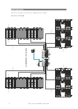
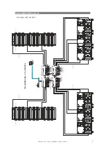
Page 8: ...IGURATIONS 8 Next find two examples You will find more configurations on our website Example with UX 218A Manual del Usuario UX series User s Manual 24 x AERO 40A 18 x UX 218A DASNET RACK99 DASNET RAC...

Page 9: ...9 Manual del Usuario UX series User s Manual Example with UX 221A CONFIGURATIONS cont d 24 x AERO 40A 12 x UX 221A DASNET RACK99 DASNET RACK99 DASNET RACK99 DASNET RACK99...

Page 10: ......

Page 11: ......

Page 12: ......

Page 13: ......

Page 14: ...rse order when switching off turning self powered units off before any other element in the sound system Disconnect the device by removing the mains connector from the mains socket The mains connector...

Page 15: ...gradation the maximum number that can be daisy chained is given by the formula Zc 10Zs where Zc is the load impedance and Zs is the output impedance of the equipment driving the enclosure mixer consol...

Page 16: ...AC the lighting equipment and the UNIT are connected to the same phase 1 Bad or loose AC connection to the UNIT or the mains outlet 2 Faulty AC cable 3 Internal fuse blown SOLUTION 1 Check that the mi...

Page 17: ...ic devices can be damaged when exposed to water or moisture The amplifiers must be protected UX when installed outdoors A rain protector is supplied with each self powered unit UX The rain protector i...

Page 18: ...lements exposed to material fatigue due to friction and load variation the following ratios must be met 5 1 for steel cable slings 4 1 for steel chain slings and 7 1 polyester slings Thus an element w...

Page 19: ...ase of the ANL 2 eyebolt this means that the 200 kg working load becomes 60 kg at 45 degrees Do not use eyebolt flying if the load angle is higher than 45 degrees Note As always when we handle heavy l...

Page 20: ...Using this dolly platform we can stack and transport up to two units and care should be taken to avoid roll over when moving them As an example these platforms can be seen in the next figures Note whe...

Page 21: ...r bar could be added This is shared with AERO 40A systems so that PICKUP AX AE40S3 allows for easy combining with these line array systems These accessories can be seen in the figures below Next we ll...

Page 22: ...ts go forward and which ones go backwards in cardioid configurations In our example since it is not a cardioid configuration all units go forward We ll place another unit on top of the one we already...

Page 23: ...ke we previously did with the lower unit Place the side parts of the AX UX218 each on its correct side check the silk screening lining up holes of the quick release pins as shown Next engage the quick...

Page 24: ...in the side of the AX parts indicated by Ease Focus using the quick release pins Remember that one pick up bar only provides a single pick up point If another pick up point is required an additional...

Page 25: ...of AERO 40A below the group of UX 218A R In this example two groups of 4 AERO 40A will be attached To prepare groups of 4 AERO 40A units on PL 40S platforms and select inter box angles consult the rig...

Page 26: ...o groups together using quick release pins Observe the indications present in the silkscreen lettering and use the AERO 40A rigging manual RM_AE40_03 as additional information Furthermore with the hel...

Page 27: ...her you can start selecting angles for AERO 40A units according to the angles indicated by Ease Focus software and according to the indications in the AERO 40A rigging manual RM_AE40_03 Remember that...

Page 28: ...and remove the PL 40S dolly platform Next lift the assembly so as to leave room for the second group of AERO 40A as stated our example will use a total of 8 AERO 40A For the second group proceed as wi...

Page 29: ...sult can be seen in the attached figure For disassembly and transport it is again advisable that you go through the AERO 40A rigging manual RM_AE40_03 that can be found on our website UX 218A R units...

Page 30: ...y the shield affects both signal conductors in the same way At the device s input the two signals get summed with opposite sign so that noise is cancelled out while the programme signal doubles in lev...

Page 31: ...ve its maximum performance and could have interferences There are 4 different types of cables The main feeds which include power and a STP CAT7 cable These cables are named eCP_xx xx refers to cable l...

Page 32: ...8 DAS 4 USA DAS Audio Asia PTE LTD 3 Temasek Avenue Centennial Tower 34 36 Singapore 039190 Tel 65 6549 7760 DAS Audio Group S L C Islas Baleares 24 46988 Fuente del Jarro Valencia SPAIN Tel 34 96 134...

Reviews: