background image


TMS3.0 

Internal Confidential


Installation Manual 


16 

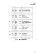
Red 

Lighting 


Harness Failure 

Red 

Blinking 

500ms 

Fault Code 

Power 

(Key off) 

Yellow 

Blinking 

1,000ms 

Mbat Sleep (Sleep Vbat Event) 

Yellow 

Blinking 

1,000ms 

Deep mode (Sleep Deep Event) 

Yellow 

Blinking 

1,000ms 

Wake up (in Mbat Sleep status) 

LTE 

Red 

Blinking 

500ms 

LTE Module / USIM Fault 

Yellow 

Lighting 


Unregistered (Roaming Failed) 

Yellow


Blinking 

1,000ms 

Registering 

Green


Lighting 


Normal - Standby 

Green 

Lighting


500ms 

Data Sending / Receiving 

SAT 

Green 

Lighting


Satellite in View 

Yellow 

Lighting


No Satellite in View 

Green 

Blinking 

500ms 

Data Sending / Receiving 

Red 

Lighting


Antenna Disconnected (Short/Open) 

Red 

Blinking 

500ms 

SAT Module Fault 

GNSS 

Yellow 

Lighting


GPS Satellite is not sensed. 

Green 

Lighting


Normal 

Red 

Lighting


Antennal Non-Connection 

Red 

Blinking 

500ms 

GNSS Module Fault 

Wi-Fi 

Yellow 

Lighting


Wi-Fi is not sensed. 

Green 

Lighting


Normal 

Red 

Lighting


Antennal Non-Connection 

Red 

Blinking 

500ms 

WiFi Module Fault 

Eth Port 

Green


Lighting


Link Connection 

Green


Blinking 


Data Transmission & Reception 

Eth Port 

Green


Lighting 


Link Connection 

Green


Blinking 


Data Transmission & Reception 

Tab. 3.5        TMS3.0 LED Specification 


Summary of Contents for TMS3.0

Page 1: ...al keep it well and if the person in charge is changed be sure to hand over this manual to the successor and let he she use the product correctly The content and image in this manual can be changed without notice by reason of product s function improvement or etc The content of this manual is protected by copyright Therefore do not change the content of this manual without permission of our compan...

Page 2: ...cument Version Date Description V1 0 2019 02 19 Initial release V2 0 2019 07 01 2nd release Type A removed LTE Connector V3 0 2020 09 14 3rd release Add FCC CE IC requirement Iridium GPS WiFi Connector changed LED Specification changed V3 1 2020 09 16 4th release Changed PMN ...

Page 3: ...roduct Handling 6 2 System Overview 9 3 Product Interface Specification 10 3 1 Classification By Product 10 3 2 Product Specification 13 3 3 Product Interface 13 3 4 Product Antenna Specification 15 3 5 LED Specification 15 4 Installation Preparation 17 4 1 Installation Method 17 ...

Page 4: ...e Of TMS3 0 Type C 11 Fig 3 4 Overall Shape Of TMS3 0 Type D 12 Fig 3 5 Front Common Connector Shape Of TMS3 0 13 Fig 3 6 Rear Connector Shape Of TMS3 0 Type A 14 Fig 3 7 Rear Connector Shape Of TMS3 0 Type B 14 Fig 3 8 Rear Connector Shape Of TMS3 0 Type C 14 Fig 3 9 Rear Connector Shape Of TMS3 0 Type D 14 Fig 4 1 Installation Block Diagram Of TMS3 0 17 Fig 4 2 Mounting Example of TMS3 0 18 ...

Page 5: ...Installation Manual 5 Tables Tab 3 1 TMS3 0 Classification By Product 10 Tab 3 2 TMS3 0 Product Specification 13 Tab 3 3 TMS3 0 Interface Specification 15 Tab 3 4 TMS3 0 Antennal Specification 15 Tab 3 5 TMS3 0 LED Specification 16 ...

Page 6: ... product can cause loss of life and property by electric shock breakdown malfunction static electricity etc Do not disassemble repair remodel this product recklessly If repair is needed call Helpdesk 82 1588 7080 Strict Observance Of Operation Condition This product normally operates in the condition described in product specification However if the product keeps operating in condition that it is ...

Page 7: ...ay cause harmful interference to radio com munications However there is no guarantee that interference will not occur in a particular installation If this equipment does cause harmful interference to radio or television recep tion which can be determined by turning the equipment off and on the user is encouraged to try to correct the interference by one or more of the following measures Reorient o...

Page 8: ... des emetteurs recepteurs exempts de licence qui sont conformes aux RSS exempts de licence d Innovation Sciences et Developpement economique Canada Son fonctionnement est soumis aux deux conditions suivantes 1 Cet appareil ne doit pas provoquer d interferences 2 Cet appareil doit accepter toute interference y compris les interferences qui peuvent provoquer un fonctionnement indesirable de l appa r...

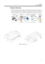
Page 9: ...real time monitoring of equipment operating information and state information in a remote place through mobile communication or satellite communication and through the real time monitoring user dealer customer can raise efficiency of equipment management Fig 2 1 Front Rear View ...

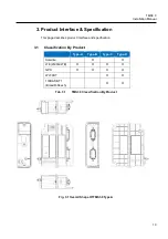
Page 10: ...on This page describes product interface and specification 3 1 Classification By Product Type A Type B Type C Type D Satellite O O LTE 2G 3G LTE O O O O GPS O O O O Wi Fi BT O O 100BASE T1 BroadR Reach O O Tab 3 1 TMS3 0 Classification By Product Fig 3 1 Overall Shape Of TMS3 0 Type A ...

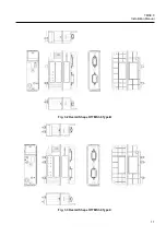
Page 11: ...TMS3 0 Internal Confidential Installation Manual 11 Fig 3 2 Overall Shape Of TMS3 0 Type B Fig 3 3 Overall Shape Of TMS3 0 Type C ...

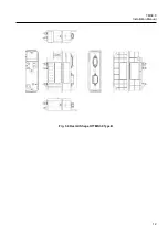
Page 12: ...TMS3 0 Internal Confidential Installation Manual 12 Fig 3 4 Overall Shape Of TMS3 0 Type D ...

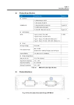
Page 13: ...E GPS Type B Power LTE SAT GPS Type C Power LTE GPS WiFI Ethernet 1 2 Type D Power LTE SAT GPS WiFi Ethernet 1 2 7 LEDs Power DC Input Voltage 12 24VDC Consumption Power Max 10 18W based on 24V Battery Charging product D type Internal Battery TLI 1550 Cell X 3 TADIRAN Physical Specification Size H x W x D 174 x 122 x 52 4mm Operation Temperature 30 75 Operation Humidity 10 95 RH Storage Temperatur...

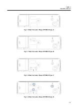
Page 14: ...idential Installation Manual 14 Fig 3 6 Rear Connector Shape Of TMS3 0 Type A Fig 3 7 Rear Connector Shape Of TMS3 0 Type B Fig 3 8 Rear Connector Shape Of TMS3 0 Type C 1 2 3 Fig 3 9 Rear Connector Shape Of TMS3 0 Type D ...

Page 15: ...ASE T1 x 2 Serial RX TX DTM13 12PA Tab 3 3 TMS3 0 Interface Specification 3 4 Product Antenna Specification Item Part No Connector Type Length mm GPS HGPS AX 0108A 04 SMA Male 3320 Iridium GPS HIRD SG 0147A 01 Iridium TNC Male Standard GPS SMA Male 3320 Wi Fi BT WLAN 2458 LP S SMA 0 15 MIMO 2 SMA Male 3320 Tab 3 4 TMS3 0 Antennal Specification 3 5 LED Specification Item Color State Interval Descri...

Page 16: ...AT Green Lighting Satellite in View Yellow Lighting No Satellite in View Green Blinking 500ms Data Sending Receiving Red Lighting Antenna Disconnected Short Open Red Blinking 500ms SAT Module Fault GNSS Yellow Lighting GPS Satellite is not sensed Green Lighting Normal Red Lighting Antennal Non Connection Red Blinking 500ms GNSS Module Fault Wi Fi Yellow Lighting Wi Fi is not sensed Green Lighting ...

Page 17: ...allation Preparation 4 1 Installation Method Fig 4 1 Installation Block Diagram Of TMS3 0 Blue Colored Location Screw Hole Installation Mounting Height Under 2m Screw Specification PN S0504653 M6X1 0X16 Surface treatment Black Strength 8 8 Material SM45C SM50C ...

Page 18: ...TMS3 0 Internal Confidential Installation Manual 18 Fig 4 2 Mounting Example of TMS3 0 ...

Reviews: