User Manual
UMN:CLI
V5824G
227
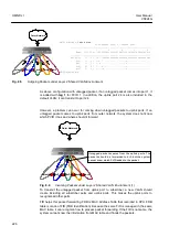
Fig. 8.7
Incoming Packets under Layer 2 Shared VLAN Environment (2)
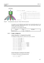
In conclusion, to use the V5824G as Layer 2 switch, user should add the uplink port to all
VLANs and create new VLAN including all ports. If the communication between each
VLAN is needed, FID should be same.
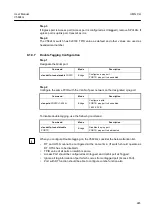
To configure FID, use the following command.
Command
Mode
Description
vlan fid
VLANS FID
Bridge
Configures FID.
8.1.11
Sample Configuration
Sample Configuration 1: Configuring Port-based VLAN
The following is assigning br50, br3, and br4 to port 2, port 3, and port 4.
SWITCH(bridge)#
vlan create
br50
SWITCH(bridge)#
vlan create
br51
SWITCH(bridge)#
vlan create
br200
SWITCH(bridge)#
vlan create
br250
SWITCH(bridge)#
vlan create
br500
SWITCH(bridge)#
vlan add
br50 5/1,6/1
untagged
SWITCH(bridge)#
vlan add
br51 5/2,6/2
untagged
SWITCH(bridge)#
vlan add
br200 t/1-t/16
tagged
SWITCH(bridge)#
vlan add
br250 t/1-t/16
tagged
SWITCH(bridge)#
vlan add
br500 t/1-t/16
tagged
SWITCH(bridge)#
vlan pvid
5/1,6/1 50
SWITCH(bridge)#
vlan pvid
5/2,6/2 51
SWITCH(bridge)#
vlan pvid
t/1-t/16 1
SWITCH(bridge)#
show vlan
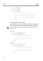
Sample Configuration 2: Deleting Port-based VLAN
The following is deleting br3 among configured VLAN.
SWITCH(bridge)#
vlan del
br3 3
SWITCH(bridge)#
exit

