User Manual
UMN:CLI
V8102
369
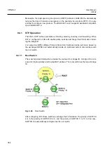
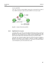
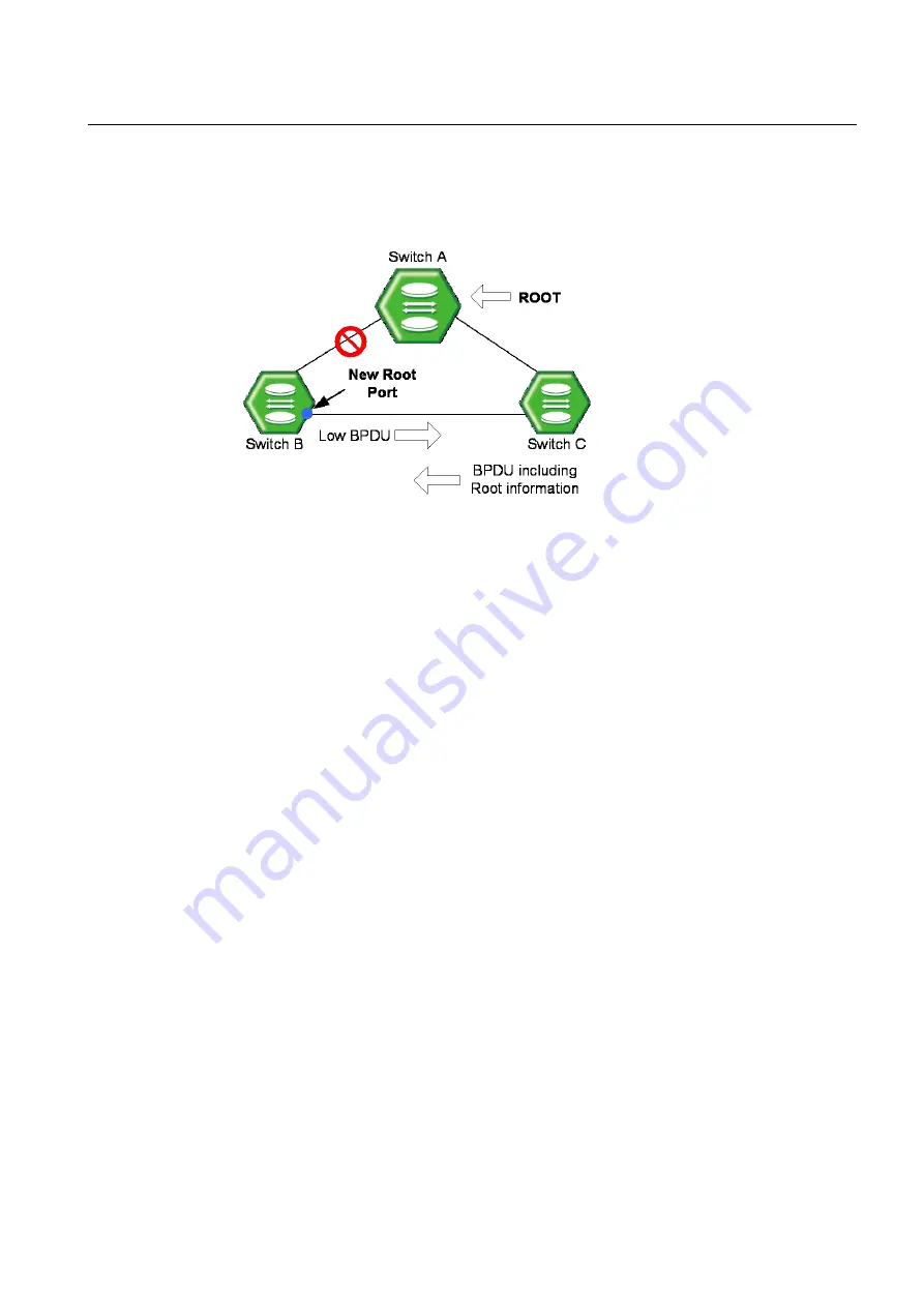
and it forwards BPDU.
In this case, the switch C transmits BPDU including the root information to the switch B.
Thus, SWITCH B configures a port connected to SWITCH C as the new root port.
Fig. 9.25
Example of Receiving Low BPDU
9.4.2.3
Rapid Network Convergence
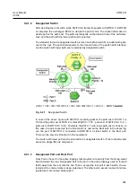
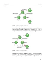
In the figure below, a new link is connected between SWITCH A and the root. Root and
SWITCH A are not directly connected, but indirectly connected through SWITCH D. After
SWITCH A is newly connected to the root, packets cannot be transmitted between the
ports because the state of two switches becomes listening, and no loop is created.
In this state, if the root transmits BPDU to SWITCH A, SWITCH A transmits new BPDU to
SWITCH B and SWITCH C, then SWITCH C transmits new BPDU to SWITCH D.
SWITCH D, which received BPDU from SWITCH C, turns the port connected to SWITCH
C into blocking state to prevent the loop after the new link.


