background image

CONNECTIONS AND EMC PRECAUTIONS 


CONNECTOR DETAILS 

 
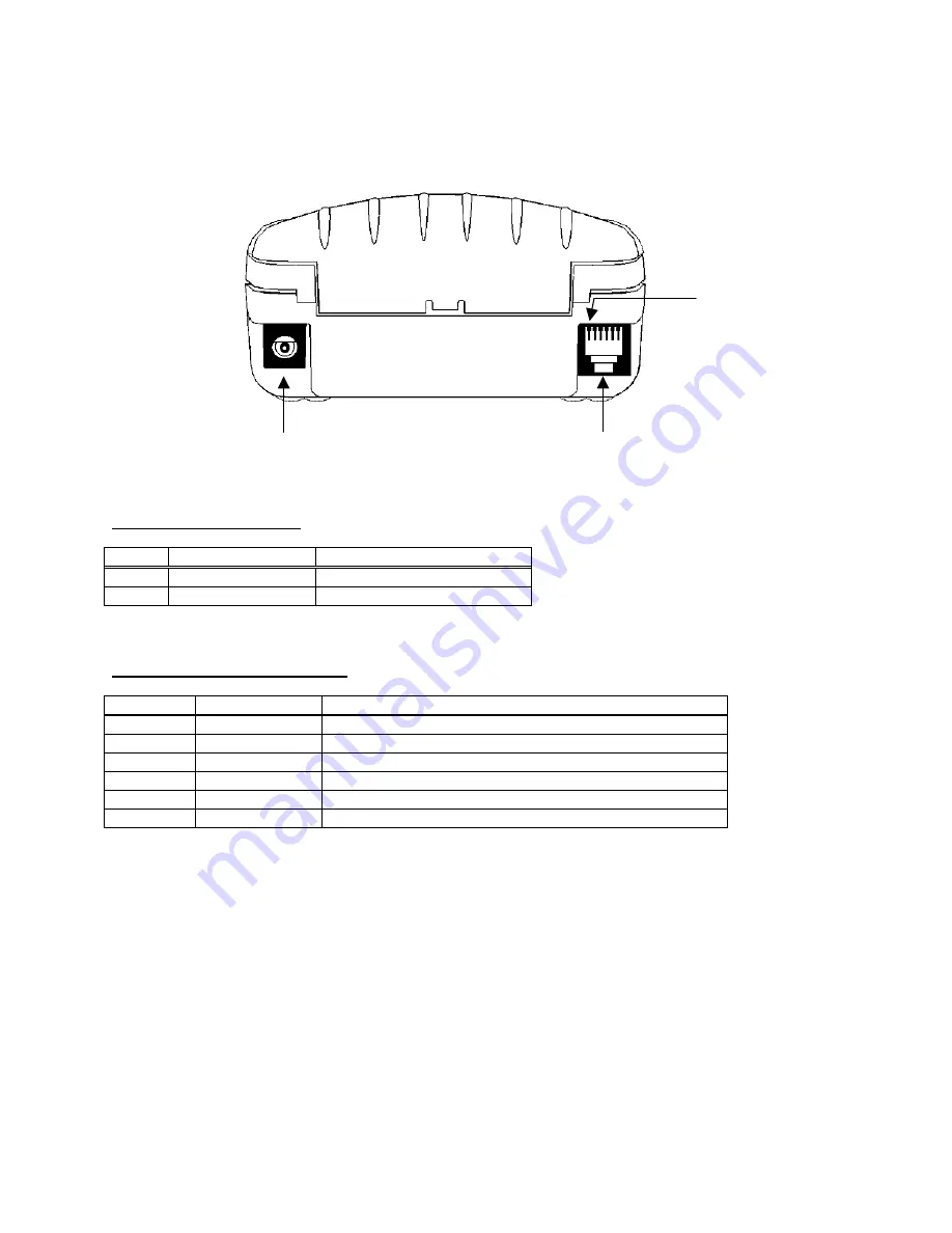
The printer has two user connectors shown below: 
 

Pin 1 

RJ12 Combined Data Socket 

Charger Input 


CONNECTOR PINOUTS 


Charger Input Socket Detail 


Pin Dimension 

(mm) Function 

Inner 

Inside 

 Ø 2.5  

Positive  / Charger  Input 

Outer 

Outside   Ø 5.5  

Negative / 0V Common 

 
The maximum insertion length is 12 mm. 
 

RJ12 Combined Data Socket Detail 


Pin Signal 

Direction 

Description 

To Printer 

Optional Charger Input 

2 To 

Printer 

Wake-up 

Input 

To Printer 

RS-232 Rx data 

To Host 

RS-232 Tx data 

5 To 

Host 

RS-232 

Busy 

--- 

0V Common (RS-232 signal return and Charger return) 


BATTERY CHARGER DETAILS 

 
The printer monitors charge current into the printer, but does not regulate it in anyway.  In order to fully and safely 
charge the batteries, use only Dascom Battery Charger Adapters.


Caution:  This connection is for a current-regulated battery charger only.  Do not connect a standard voltage 

power supply.  Serious damage may result from inappropriate connections.


COMBINED DATA/CHARGER ADAPTOR CABLE 

 
An optional serial data cable suitable for connecting the printer to a standard PC is available.  This cable features an 
integrated charger connector in the housing of the DB-9 connector.  For trickle charging, the charger may optionally 
be connected directly into the printer’s connector, or indirectly into the connector in the data cable, thus giving the 
maximum system wiring flexibility.     
 
The connections to a standard PC COM port are as follows: 

11 

Summary of Contents for DP-510

Page 1: ...DP 510 and DP 520 Operators Manual Dascom Part Number 5206788 Rev A...

Page 2: ......

Page 3: ...ing and Fonts 8 Graphics Printing and Other Programming Modes 8 Interface Details 9 RS 232 Serial Interface Applies to ALL MODELS 9 IrDA Interface Applies to DP 510 IrDA and DP 520 IrDA only 9 Bluetoo...

Page 4: ......

Page 5: ...nd improve the firmware in its printer products at any time While every effort is made to ensure backward compatibility no guarantee in this respect is given or implied The DP 510 and DP 520 include a...

Page 6: ...pt Bluetooth models which are factory set to 4 minutes but is programmable from the host In sleep mode power consumption is negligible but data stored in the buffer are lost Special routines allow for...

Page 7: ...ause the paper has run out or the lid is open The printer will automatically enter spooling mode when the paper is out when the paper lid is open if some other error condition occurs or alternatively...

Page 8: ...rged and disconnected Before use the battery must be connected see below and then fully charged CONNECTING THE BATTERY PACK The procedure for connecting the battery pack is as follows 1 Remove the scr...

Page 9: ...ich takes about 15 hours The capacity of the battery pack when fully charged will normally be sufficient to print normal text on about four full rolls of paper However the amount of printing which can...

Page 10: ...e the Lid Release Button forwards until the Lid springs open 2 Unwind a small amount of paper from the roll and Insert the Paper Roll into the Printer 3 Close the Lid down and the paper is loaded Afte...

Page 11: ...connected Status Indicator Pattern Table Pattern Battery Buffer Mode Constant Green Running Normal Fast Flashing Green Running Spooling Long Green Short Red Battery Low Normal Short Green Short Red B...

Page 12: ...nd from the host Paper Out condition or Paper Lid open condition being sensed an error condition e g head over temperature battery over voltage etc In spooling mode the buffered data are stored withou...

Page 13: ...up sensor is reduced It may be necessary to bring the host IrDA device fairly close to the printer before it will wake up Once awake the printer will respond to communications from an IrDA compliant p...

Page 14: ...he Bluetooth link The printer must be awake before a Bluetooth link may be established and any data can be transferred to it via the Bluetooth interface Because of this the default Sleep Period for th...

Page 15: ...monitors charge current into the printer but does not regulate it in anyway In order to fully and safely charge the batteries use only Dascom Battery Charger Adapters Caution This connection is for a...

Page 16: ...ge 3V 12V to keep the printer awake permanently In this case the printer will attempt to go to sleep if the normal inactivity time out elapses but will merely reset and then re start This behavior may...

Page 17: ...attery cover of the printer as shown below Remove the two break outs using a small screwdriver When attaching to a belt the bracket should be put on the printer first and then the entire assembly clip...

Page 18: ...ace is configured Next CONNECT THE PRINTER TO THE PC The back panel of a PC typically includes several D type keystone shaped connectors One of these is usually DB 9 Plug male COM1 Serial port for mou...

Page 19: ...ch fully support the DP 510 and DP 520 are available for PDA s and other Pocket PC platforms from www fieldsoftware com When using these tools select the Able Systems AP1300 AP1310 Your Application Pr...

Reviews: