12
13
5. Trouble Shooting Guide
Subwoofer output
Abnormal
Replace SW Jack
Refer to VOL IC400
Checkif the
IC400 PIN 36
waveform is OK.
Checkif the
IC803 PIN 4
waveform is OK.
Check if the SW
Jack is OK
OK
No
No
Yes
No
Refer to SW AMP IC803
Yes
Yes
REMOTE CONTROL
Abnormal
Refer to RMC
Check if the IC750
PIN2 is OK.
Refer to MICOM
Yes
No
MAIN VOLUME &
CHANNEL Level
Abnormal
Refer to Loader PCB
Check if the
IC300, IC400 is
OK.
Refer to FRONT PCB
Yes
No
H/P outout Abnormal
Refer to H/P AMP IC404
Checkif the
IC404 PIN 1, 7
waveform is OK.
Refer to H/P
Control circuit
No
Yes
Check if the
H/P Jacknis OK.
Yes
Replace H/P Jack
No
Audio Block
5. Trouble Shooting Guide
Insert AC Power Cord.
Check PATTERN and
RESOLDERING.
Check if the FL700
PINS are OK
Yes
No
Check if the
FRONT POWER
is OK.
Replace XC750
Check if the
IC750 OSC PIN wave-
form is OK.
Yes
No
No
Yes
Check if the IC750
PIN(72) is OK.
Refer to POWER
SUPPLY circuit.
No
Re connect it.
Check if the
CW700 is OK ?
No
Yes
Yes
LED ON
LED OFF
STANDBY ON
Yes
Yes
Does initial work ?
Yes
No
Refer to
MICOM circuit.
Check if the
REMOCON is OK.
Yes
Check if ALL
BUTTONS are OK.
Check if the
VOLUME is OK.
Yes
Yes
Check if the
HEADPHONE is OK.
Yes
Front PCB OK
Check if the
HEADPHONE Jack
is OK.
Yes
Check if the
POWER is OK.
Yes
Check if the
J700 PIN(4)
is High.
Yes
Check MAIN PCB
Refer to Power
Supply circuit.
Check J700 circuit.
Replace H/P JACK
Check if the
IC750 PIN(14) (15)
is OK.
Yes
Check if the
VR700,HR714,HR715
is OK.
Yes
Check if the
POWER PART of the
FRONT is OK.
Yes
Refer to
MICOM circuit.
Refer to Power
Supplycircuit.
Replace VR700,
HR714, HR715
Check if the
IC750 PIN(22),(23)
is OK.
Yes
Check if the
POWER PART of the
FRONT is OK.
Yes
Refer to
MICOM circuit.
Refer to POWER
SUPPLY circuit.
Refer to KEY-IN line
No
No
No
No
No
No
No
No
Check if the
IC700 PIN(1) is OK.
Yes
Check if the
POWER PART of the
FRONT is OK.
Yes
Check if the
REMOCON waveform of
the IC750 PIN(2)
Yes
Refer to
MICOM circuit.
Refer to Power
Supply circuit.
Replace IC700
Check RMC circuit.
No
No
No
No
No
No
No
1
2
1
2
No
No
Refer to POWER
SUPPLY circuit.
CW712 Pin(1) : 5V
Front Circuit
Summary of Contents for DHC-X100N
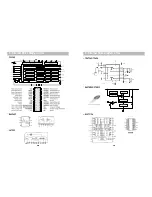
Page 11: ...8 Internal Block Diagram of ICs M62446AFP 21 8 Internal Block Diagram of ICs 20 ES6638 NJM4558...
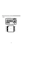
Page 12: ...8 Internal Block Diagram of ICs 22 AK5381...
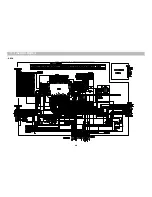
Page 13: ...9 Block Diagram 23...
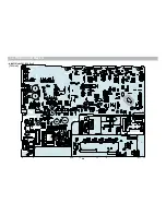
Page 14: ...10 Wiring Diagram 24...
Page 15: ...11 Schematic Diagram FRONT 25...
Page 16: ...11 Schematic Diagram Mi COM 26...
Page 17: ...11 Schematic Diagram INPUT VIDEO 27...
Page 18: ...11 Schematic Diagram AMP 28...
Page 19: ...11 Schematic Diagram POWER 29...
Page 20: ...12 Printed Circuit Diagram 30 TOP View MAIN PCB with DHC 100N Front...
Page 21: ...12 Printed Circuit Diagram Bottom View 31...
Page 22: ...12 Printed Circuit Diagram 32 Bottom View Top View IN OUT...
Page 23: ...Bottom View Top View 12 Printed Circuit Diagram FRONT DHC X150N Only 33...
Page 24: ...14 Exploded View and Mechanical Parts List DHC X100N Only 34...
Page 25: ...14 Exploded View and Mechanical Parts List 35...
Page 26: ...14 Exploded View and Mechanical Parts List DHC X150N Only 36...
Page 27: ...14 Exploded View and Mechanical Parts List 37...


