6. DVD Program Download Method
MPEG PROGRAM DOWNLOAD METHOD
INSERT THE UPDATE DISC INTO THE DISC TRAY, THEN THE DVD RECEIVER READS
THE DISC AND UPDATE THE FIRMWAFE ITSELF AS FOLLOWINGS.
@ INSERT THE UPDATE DISC.
NO
STATUS
VFD
MONITOR
SET CONDITION
1
STARTING UPDATE
DISC LOADING
LOADING
DOOR CLOSE
2
DETECT THE UPDATE DISC
TRK
▶
000 0:00:00
FLASH
ES6629.ROM
READING
DOOR CLOSE
3
READ
WRITING/ERASE
4
COMPLETED THE READ
DONE
DOOR OPEN
5
END
DOOR OPEN
DOOR OPEN
NOTE :
2) AFTER COMPLETED, POWER OUT AND IN AGAIN.
1) AFTER DOOR OPEN, EJECT THE UPDATE DISC.
CAUTION :
WHILE DOOR OPEN, IF CD DOOR IS CLOSED BY TOUCH, OR POWER BUTTON
IS PRESSED THEN FLASH MEMORY WILL BE ERASED.
TRK
▶
000 0:00:00
TRK
▶
000 0:00:00
15
14
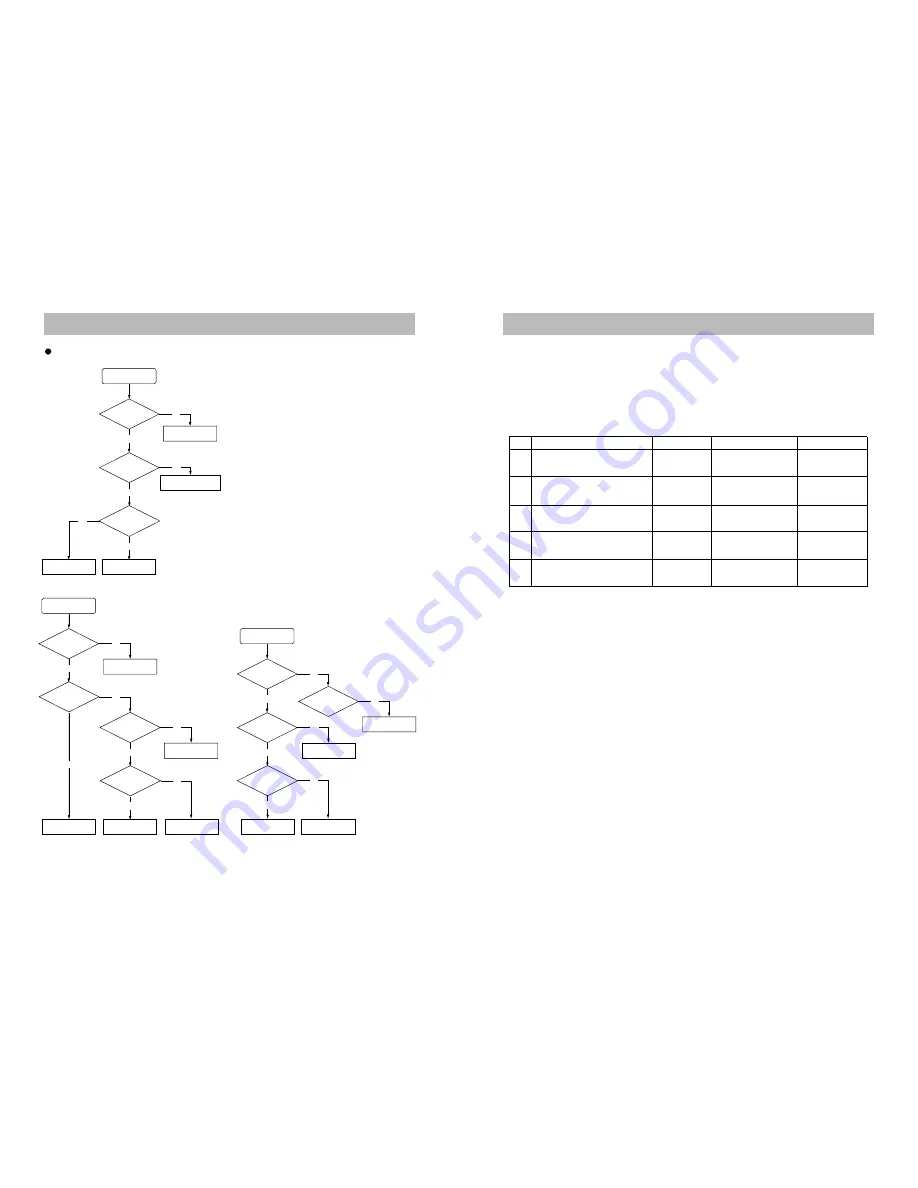
5. Trouble Shooting Guide
Refer to Loader circuit.
Check if the
SPK OUT is OK.
Check if CW712
is OK.
SOUND Abnormal
VIDEO OUT Abnormal
Refer to VIDEO JACK
Check if the VIDEO
JACK is OK
OK
OPEN/CLOSE Abnormal
Replace DECK
MECHA DVD
Check Power Supply circuit.
OK
Replace to POWER
Supply circuit.
Check if the CW600
is OK
Check if the IC600
PIN(8) is OK
Reconnect it
Check if the IC600
PIN(1) is OK
Replace it.
Check if the FRONT
CONTROL is OK.
Check if the CN703
cable is nomally.
Refer to MICOM circuit.
Check if the IC750
is OK.
Check Connection
CW610 is OK.
Refer to AMP circuit.
Check if the
IC301, IC302, IC303
is OK.
Yes
Yes
No
No
No
Yes
Yes
No
Refer to MICOM circuit.
Yes
No
No
Yes
Refer to MICOM circuit.
No
No
Yes
Yes
No
Yes
No
No
Yes
DVD Block
Summary of Contents for DHC-X100N
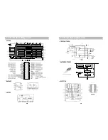
Page 11: ...8 Internal Block Diagram of ICs M62446AFP 21 8 Internal Block Diagram of ICs 20 ES6638 NJM4558...
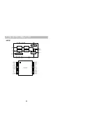
Page 12: ...8 Internal Block Diagram of ICs 22 AK5381...
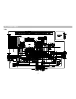
Page 13: ...9 Block Diagram 23...
Page 14: ...10 Wiring Diagram 24...
Page 15: ...11 Schematic Diagram FRONT 25...
Page 16: ...11 Schematic Diagram Mi COM 26...
Page 17: ...11 Schematic Diagram INPUT VIDEO 27...
Page 18: ...11 Schematic Diagram AMP 28...
Page 19: ...11 Schematic Diagram POWER 29...
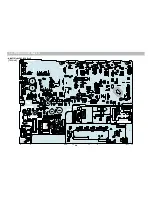
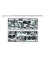
Page 20: ...12 Printed Circuit Diagram 30 TOP View MAIN PCB with DHC 100N Front...
Page 21: ...12 Printed Circuit Diagram Bottom View 31...
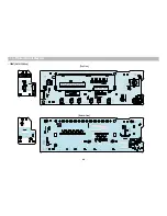
Page 22: ...12 Printed Circuit Diagram 32 Bottom View Top View IN OUT...
Page 23: ...Bottom View Top View 12 Printed Circuit Diagram FRONT DHC X150N Only 33...
Page 24: ...14 Exploded View and Mechanical Parts List DHC X100N Only 34...
Page 25: ...14 Exploded View and Mechanical Parts List 35...
Page 26: ...14 Exploded View and Mechanical Parts List DHC X150N Only 36...
Page 27: ...14 Exploded View and Mechanical Parts List 37...


