background image

89 • dap4 User Manual 

COMPRESSOR SHORT-CYCLE ALARM

1.  Compressor shot-cycle alarm is programmable (See Menu K – Alarms and Limits).  A compres-

sor short-cycle alarm will activate if the compressor has been energized ten (10) times in a one 

(1) hour period. 

2.   The alarm is a warning only.  Compressor operation will continue. 

3.   One cycle is a combination of compressor starts for cooling or dehumidification functions.  

4.  If the compressor is started ten (10) times in a one (1) hours period, the alarm will be activated 

and the message “Comp Short- Cycle” will be displayed on the display module.

5.   The compressor short-cycle time delay will be increased from five (5) to six (6) minutes for the 

next hour.

6.   The short-cycle alarm will not clear until a one (1) hour period has passed with less than ten 

(10) compressor starts.

POWER PROBLEM or RESTART MODE

The Power Problem or Restart Mode is programmable (See Menu K – Alarms and Limits).  There 

are three available selections:

1. “Auto, No Alarm” (Automatic:  No Message or Alarm).  The unit will automatically start after a 

power failure or reset. No audio alarm will sound.  No message will be displayed on the display 

module.

2. “Auto, With Alrm” (Automatic:  Message, Audio Alarm & Relay).  The unit will automatically re-

start after a power failure or reset.  The audio alarm will be activated and the message “ Power 

Failure Restart” will be displayed on the display module.   

3. “Man, Clr Alarm” (Manual:  Message, Audio Alarm & Relay).  The unit will NOT automatically 

restart after a power failure or restart.  

FAN FAILURE ALARM IN CHILLED WATER SYSTEM

Chilled water unit with dap4 controller and plug fans currently has eight different fan speed control 

modes. Each mode is modified to add the following fan speed control logic when a Fan Failure 

alarm is detected. Fan failure alarm will be detected by fan alarm contact; this sends an alarm 

signal to digital input DI12 of the dap4. 

When a Fan Failure alarm is detected, the fan speed will automatically ramp up to 100%. If dap4 

is programmed to constant speed mode or to maximum speed if dap4 is programmed to other 

fan speed control modes. While the Fan failure alarm is active, the audio alarm will sound and an 

alarm message “Fan Fails, Check fans” display on dap4 LCD screen. The reheat and humidifier 

will be inhibited during fan failure alarm but the chilled water valve will continue to operate. The 

fan speed control should automatically go back to the normal operation mode when fan failure no 

longer exists.  

Note: This logic does not affect any menu settings

Summary of Contents for dap4 touch

Page 1: ...dap 4 Installation Operation Maintenance Manual TM Data Aire Inc 230 W BlueRidge Avenue Orange CA 92865 www dataaire com...

Page 2: ...Data Aire Inc reserves the right to make design changes for the purpose of product improvement or to withdraw any design without notice...

Page 3: ...Changing the Service Level Password 12 Menus Menu A ON OFF 13 Menu B Setpoints 14 Menu C Clock Scheduler 16 Menu D Input Output 20 Menu E Historical Data 23 Menu F Information 25 Menu G Network Confi...

Page 4: ......

Page 5: ...mable solid state control module LED Illuminated Keys Six highly reliable keys allow movement through the menus Backlit Liquid Crystal Display LCD Information is displayed and presented in a format t...

Page 6: ...c Compressor Rotation Periodically rotates the lead lag compressor sequence to balance run times Automatic Reheat Element Rotation Rotates the staging sequence to balance the heating elements run time...

Page 7: ...may require additional components and or sensors WARNINGS AND ALARMS DISPLAYED HIGH TEMPERATURE WARNING LOW TEMPERATURE WARNING HIGH HUMIDITY WARNING LOW HUMIDITY WARNING POWER FAILURE RESTART NO AIR...

Page 8: ...RESTART RESTART MODE SYSTEM START DELAY MANUAL DIAGNOSTICS MESSAGE FOR OPTIONAL ALARM 1 2 3 and 4 PERSON TO CONTACT ON ALARM DELAY FOR OPTIONAL ALARM 1 2 3 and 4 WATER VALVE MODE COMPRESSOR ASSIST TO...

Page 9: ...The display panel has a backlit LCD liq uid crystal display There are six keys on the face of the display panel to retrieve or enter settings Control Module Display Module Button Functions Allows vie...
Page 10: ...urned ON at any time Hold the Esc key for approximately 5 seconds The dis play will continue to scroll and display messages At the same time the unit status is changed to Unit On Once powered there wi...

Page 11: ...Level Password setting from the factory is 0000 The cursor will be flashing by the Security Access message at the top of the screen Press the ENTER key to move the cursor The cursor will flash at the...

Page 12: ...e changed by doing the following Enter the Main Menu by pressing the Menu key You will be prompted to Insert the Service Level password Enter the current password as previously explained Press the Men...

Page 13: ...s the ENTER key to save the setting If selecting SWITCH OFF the STATUS will change to OFFbyKey The unit will be OFF If selecting SWITCH ON the STATUS will change to UnitOn The unit will be ON When swi...

Page 14: ...nge for CW 65 105 F DEADBAND 2 0 F Temperature Deadband range 2 5 F STAGE TO STAGE 0 3 F Stage to Stage range 0 3 3 0 F ENGY SVR SETPT 50 0 F Setpoint range 40 0 60 0 F DEADBAND 1 0 F Deadband range 1...

Page 15: ...nce the desired setpoint value has been changed press the ENTER key to move to the next setting or until the cursor is at the top of the screen Exit the Setpoint Menu by pressing the Esc key The displ...

Page 16: ...the UP and DOWN keys will change the value The day will automatically change when the date has been altered Press the ENTER key until the cursor is in the title block upper left hand corner Press the...

Page 17: ...ected Press the ENTER key The cursor will flash on the Copy to Day Pressing the UP or DOWN key all the days of the week can be viewed The Copy to function allows the user to copy setting from other da...

Page 18: ...e Once the correct minutes are selected press the Enter key The cursor will be positioned on the settings input Press the DOWN key to view the available selections Set Back Normal SP setpoint Turn Off...

Page 19: ...Normal SP Turn Off Set Back Once the settings are complete with the cursor in the title block press the DOWN key to advance to the next screen or press Esc to return to the Main Menu or press the Esc...

Page 20: ...menus Scroll through the menus using either the UP or DOWN keys Move Menu D to the highlighted area and press the ENTER key The following will be displayed values are for reference only Press the DOW...

Page 21: ...reference only Press the DOWN key to view the next screen The following will be displayed values are for reference only Press the DOWN key to view the next screen The following will be displayed value...

Page 22: ...ues are for reference only All screens have been viewed BY pressing the UP or DOWN keys the screens can be viewed Press the MENU key to return to the main menu Choose another menu by pressing the UP o...

Page 23: ...NTER key moving the cursor into the screen area Press the UP key and the display will show the previous alarm with time and date Continue to press the UP key to view all alarms Once the last listed al...

Page 24: ...ntil the cursor is flashing on the title line Press the DOWN key to move to next screen The screen will display the following With the cursor flashing on the title line press the UP or Down key to rev...

Page 25: ...two screens The first screen will display the following Press the UP or DOWN key to view second screen The second screen will display the following Press the MENU key to return to the main menu or pr...

Page 26: ...on has been made press the ENTER key and the cursor will move to the title block To move to the next screen press the DOWN key The following will be displayed values are for reference only The address...

Page 27: ...increase or DOWN to decrease keys the Offset can be changed Once the change has been made press the ENTER key and the cursor will move to the title block of the screen The Offset change is now entere...

Page 28: ...ove the cursor The cursor will flash at the Offset By pressing the UP to increase or DOWN to decrease keys the Offset can be changed Once the change has been made press the ENTER key and the cursor wi...

Page 29: ...u press the Esc key or to view the following screen press the DOWN key The following will be displayed values are for reference only Move the cursor to the title block by pressing the ENTER key To ret...

Page 30: ...llowing will be displayed values are for reference only Move the cursor to the title block by pressing the ENTER key To return to the Main Menu press the Esc key or to view the following screen press...

Page 31: ...0 to 99 seconds in 1 second intervals Start up Delay The range is 5 to 600 seconds in 1 second intervals Temp Units Fahrenheit or Centigrade Out Status There are five choices Sys On Dehum On Hum On Co...

Page 32: ...can be entered Modulate Min 40 100 Modulate Max 70 100 If choosing AIR PRESSURE the following will be displayed and values can be entered Modulate Min 40 100 Modulate Max 70 100 With DX if choosing PR...

Page 33: ...l semi hermetic compressors w unloading Four Tandem dual tandem scroll compressors None entry for chilled water units Lead Lag Enabled or Disabled if Disabled is selected Lead and Rotate Lead are not...

Page 34: ...e of refrigerant suction pressure Move the cursor to the title block by pressing the ENTER key stepping through all the inputs To return to the main Menu press the Esc key or to view the following scr...

Page 35: ...econd factory setting is First With three stage reheat pick either First Second or Third factory setting is First Once a selection or selections have been made move the cursor to the title block by pr...

Page 36: ...there will be no message Note E Saver Assist will only appear if either Engy Svg Cool or Aux Chill Wtr are selected Wtr Vlv Voltage 0 10 factory setting 4 7 6 9 7 10 2 10 Wtr Vlv Action Direct factor...

Page 37: ...r selections have been made move the cursor to the title block by pressing the ENTER key or press the Esc key to return normal operating mode Press the DOWN key to view the next screen The following w...

Page 38: ...tions Yes or No Note Selecting YES will reset all values back to the factory settings default If YES is selected the following message will be displayed wait resetting resetting will take a few second...

Page 39: ...ce only Available Selections Audio Mode None Full On Long Beep Short Beep Pwr Up Auto No Alarm Auto With Alarm Man Clr Alarm Maint Due Msg None The range is 0 to 1000 hours Once a selection or selecti...

Page 40: ...e the cursor to the title block by pressing the ENTER key Press the DOWN key to view the next screen The following will be displayed values are for reference only Available Selections No Water Flow Ac...

Page 41: ...F factory setting is 60 F Note If No is selected for the Hi or Lo Temp Alarm the Set Point will not be displayed Once a selection or selections have been made move the cursor to the title block by pre...

Page 42: ...to 90 RH factory setting is 60 RH Lo Humidity Alarm Yes or No factory setting is Yes Set Point The range is 10 to 65 RH factory setting is 40 RH Note If No is selected for the Hi or Lo Humidity Alarm...

Page 43: ...PUMP ON UPS ON CHK MAIN POWER UNIT IN STBY REHEAT HUM INHIBIT HUMIDIFIER INHIBITED REHEAT INHIBITED Once a selection or selections have been made move the cursor to the title block by pressing the EN...

Page 44: ...ENTER key Press the DOWN key to view the next screen The following will be displayed values are for reference only Alarm Output Function 1 See sample screen shot at end of section Alarm 1 Alarm 2 Alar...

Page 45: ...or No Low Humid Yes or No Yes or No Yes or No Yes or No Humidifier Yes or No Yes or No Yes or No Yes or No DA Low T Yes or No Yes or No Yes or No Yes or No RA Low T Yes or No Yes or No Yes or No Yes o...

Page 46: ...es or No Yes or No Yes or No Yes or No Alm SW 4 Yes or No Yes or No Yes or No Yes or No Once a selection or selections have been made move the cursor to the title block by pressing the ENTER key Press...

Page 47: ...the ENTER key Move the cursor to change the setting The following can be changed by pressing the DOWN key Channel Open or Closed Delay the range is 0 999 seconds Status Open or Closed Status can t be...

Page 48: ...llowing can be changed by pressing the DOWN key Channel Open or Closed Delay the range is 0 999 seconds Status Open or Closed Status can t be changed Once a selection or selections have been made move...

Page 49: ...hanged by pressing the DOWN key Channel Open or Closed Delay the range is 0 999 seconds Status Open or Closed Status can t be changed Once a selection or selections have been made move the cursor to t...

Page 50: ...Delay the range is 0 999 seconds Status Open or Closed Status can t be changed Once a selection or selections have been made move the cursor to the title block by pressing the ENTER key Press the DOWN...

Page 51: ...tions have been made move the cursor to the title block by pressing the ENTER key Press the DOWN key to view the next screen The following will be displayed values are for reference only Move the curs...

Page 52: ...ENTER key Press the DOWN key to view the next screen The following will be displayed values are for reference only Move the cursor by pressing the ENTER key Move the cursor to change the setting The...

Page 53: ...key to view the next screen The following will be displayed values are for reference only Move the cursor by pressing the ENTER key Move the cursor to change the setting The following can be changed...

Page 54: ...key to view the next screen The following will be displayed values are for reference only Move the cursor by pressing the ENTER key Move the cursor to change the setting The following can be changed...

Page 55: ...WN key to view the next screen The following will be displayed values are for reference only Move the cursor by pressing the ENTER key Move the cursor to change the setting The following can be change...

Page 56: ...key Press the DOWN key to view the next screen The following will be displayed values are for reference only Move the cursor by pressing the ENTER key Move the cursor to change the setting The followi...

Page 57: ...ock by pressing the ENTER key Press the DOWN key to view the next screen The following will be displayed values are for reference only Note If Enable OFF is selected the High Res Offset and Value will...

Page 58: ...a selection or selections have been made move the cursor to the title block by pressing the ENTER key Press the DOWN key to view the next screen The following will be displayed values are for referenc...

Page 59: ...y to view the next screen The following will be displayed values are for reference only With Enable OFF With Enable ON The Choose Name allows one of the following to be selected by moving the cursor t...

Page 60: ...Temp CW Ret Temp CW Sply Temp Cond Ret Temp Cond Sup Temp Power Frequency Ground Amps Neutral Amps Output Amps C Output Amps B Output Amps A Input Amps C Input Amps B Input Amps A Output V B C Output...

Page 61: ...ection or selections have been made move the cursor to the title block by pressing the ENTER key Press the DOWN key to view the next screen The following will be displayed values are for reference onl...

Page 62: ...available DO NOT ASSIGN THE SAME CHANNEL ON MORE THAN ONE ANA LOG OUTPUT Action there are two choices DIRECT AND REVERSE Minimum the range is from 0 0vdc to 10 0vdc Maximum the range is from 0 0vdc to...

Page 63: ...The following will be displayed values are for reference only Move the cursor by pressing the ENTER key Move the cursor to change the setting The following can be changed by pressing the DOWN key Cha...

Page 64: ...RE THAN ONE ANA LOG OUTPUT Action there are two choices DIRECT AND REVERSE Minimum the range is from 0 0vdc to 10 0vdc Maximum the range is from 0 0vdc to 10 0vdc To return to another Input or Output...

Page 65: ...he same primary stage compressor The delay will be increased to six 6 minutes for one 1 hour following the detection of a compressor short cycle condition even if the compressor short cycle alarm is d...

Page 66: ...adband 0 1 F 10 Position Open Current Temperature Setpoint Deadband 0 2 F 20 Position Open Current Temperature Setpoint Deadband 0 3 F 30 Position Open Current Temperature Setpoint Deadband 0 4 F 40 P...

Page 67: ...bove this range the Energy Saver Auxiliary Chilled Water Cooling will be inhibited for the amount of time set in Menu J Energy Saver Lockout Time and DX Direct Expansion cooling will take over After t...

Page 68: ...sition Open 9 The dap4 will switch the unit to DX cooling for one 1 hour after every 100 hours of continuous hours of Energy Saver or Auxiliary Chilled Water Cooling ENERGY SAVER and AUXILIARY CHILLED...

Page 69: ...t water and hot gas They are single stage Single stage operates in the follow ing manner Reheat is ON at Temperature Setpoint Temperature Deadband Reheat is OFF at Temperature Setpoint 5 Reheat will b...

Page 70: ...DC when R A temp Temp SP Temp DB 0 8 SCR Pro band 9VDC when R A temp Temp SP Temp DB 0 9 SCR Pro band 10VDC when R A temp Temp SP Temp DB SCR Pro band When temperature rises Y4 output signal 0VDC when...

Page 71: ...air temperature rises to the temperature setpoint Compressor short cycle time will not be violated 3 If dehumidification is programmed for No Reheat Limits it will remain ON until the humidity setpoin...

Page 72: ...hich it will respond after each adjustment period 3 The dehumidification sequence for chilled water units is as follows Valve is OPENED to 100 at Humidity Setpoint Humidity Deadband Valve is CLOSED at...

Page 73: ...e will open if dewpoint is increasing OR relative humidity is increasing closer to the setpoints Either high dewpoint or high relative humidity can cause the CW to open and call for dehumidification T...

Page 74: ...3 F Open 60 if return dewpoint high_dewpoint_setpoint high_dewpoint_deadband 0 4 F Open 50 if return dewpoint high_dewpoint_setpoint high_dewpoint_deadband 0 5 F Open 40 if return dewpoint high_dewpoi...

Page 75: ...lled by the discharge air temperature sensor iii An adjustable Minimum runtime for variable speed compressor with a range of 2 10 minutes is added the Factory Setting menu default value is 2 minutes i...

Page 76: ...4 Factory Settings menu is programmed to Variable fixed and Control mode is set to Return Temp There is a five 5 minute delay between start to start of the same primary stage The delay will be increas...

Page 77: ...ply is below the setpoint of the Energy saver Water Thermostat in menu B setpoint Energy Saver 2 The Energy Saver Auxiliary Chilled Water mode will operate when space temperature is between the return...

Page 78: ...rrent Temperature Setpoint 0 5 F 50 Position Current Temperature Setpoint 0 4 F 40 Position Current Temperature Setpoint 0 3 F 30 Position Current Temperature Setpoint 0 2 F 20 Position Current Temper...

Page 79: ...delay This step only applies to dual compressor system For instance SP 72 DB 2 and STS 0 3 the C2 compressor will on at 76 3 Compressors off cycle Fixed speed compressor C2 cycles off at Temperature S...

Page 80: ...tings type in dap4 Factory Settings menu is programmed to Vari Fixed and Control mode is set to Supply There is a five 5 minute delay between start to start of the same primary stage The delay will be...

Page 81: ...deadband plus Energy saver to DX change over band If the temperature rises above this range Energy Saver Auxiliary Chilled Water Cooling will be inhibited for at least 15 minutes to an hour it depend...

Page 82: ...on at Temperature Setpoint Temperature Deadband 1 F STS DB and variable speed compressor C1 has operated at 95 for at least the C2 on delay When C2 comes on variable speed compressor C1 will drop its...

Page 83: ...Variable speed compressor system Dehumidification cycles on If unit is not in cooling mode the variable speed compressor turns on when humidity is at Humidity Setpoint HSP Humidity Deadband HDB Compre...

Page 84: ...nue to finish the dehumidification cycle then reverse to temperature control cooling mode Dehumidification cycles off When humidity drops Fixed speed compressor C2 NO3 will turn off when humidity Humi...

Page 85: ...int SP 1 Deg F compressor will run at 0 0VDC If dewpoint High dewpoint SP 0 9 DegF compressor will run at 10 1V If If dewpoint High dewpoint SP 0 8 DegF compressor will run at 20 2V Etc C2 fixed speed...

Page 86: ...essor and a fixed speed compressor Dehumidification cycles on If unit is not in cooling mode C2 fixed speed compressor turns on when humidity reaches Humidity Setpoint HSP Compressor will not violate...

Page 87: ...on pressure alarm with manual reset can be enable in menu K alarm and limits of dap4 The default setting is disable If enabled when alarm counts match the programmed Lock out times the compressor will...

Page 88: ...discontinued After eleven minutes the humidity alarms are enabled HUMIDITY ANTICIPATION 1 Humidity anticipation is programmable ON or OFF See Menu J Factory Settings 2 When set to ON the humidity setp...

Page 89: ...lrm Automatic Message Audio Alarm Relay The unit will automatically re start after a power failure or reset The audio alarm will be activated and the message Power Failure Restart will be displayed on...

Page 90: ...display module until the condition is corrected FIRESTAT TEMPERATURE ALARM 1 The firestat temperature alarm is programmable from 100 to 150 F See Menu K Alarms and Limits 2 If the return air temperatu...

Page 91: ...the audio alarm is activated and a Low Humidity Warning message is displayed on the display module 3 The audio alarm is a warning only and will not prevent any of the unit functions form operating 4...

Page 92: ...until the alarm condition is corrected PERSON TO CONTACT ON ALARM 1 The person to contact on alarm is programmable See Menu K Alarms and Limits It can also be disabled 2 The alarm is a warning only a...

Page 93: ...t is required 5 The alarm will remain until the alarm condition is corrected NO WATER FLOW ALARM ACTION CHILLED WATER UNITS 1 The dap4 controller will not detect the no water flow alarm unless the chi...

Page 94: ...odule 4 The alarm is a warning only and will not prevent any of the unit functions from operating 5 The alarm will remain until the alarm condition is corrected REHEAT INHIBITED ALARM 1 The reheat inh...

Page 95: ...in until the alarm condition is corrected WATER UNDER FLOOR DETECTION ALARM 1 The water under floor detection alarm message is displayed when the alarm is activated the sensor has detected water 2 The...

Page 96: ...tting when the unit stops calling for reheat or humidification WARNING IF CUSTOMER DECIDES TO USE THIS FAN SPEED CONTROL MODE FAN SPEED CONTROLLED BY BMS DATA AIRE WILL NOT BE RESPONSIBLE FOR ANY EF F...

Page 97: ...ow menu until the dap4 receives a valid airflow value greater than the minimum allowed airflow and less than the maximum allowed airflow from a BMS This control mode requires an optional airflow measu...

Page 98: ...s are accessible through Menu J Factory Settings Either of the following may be chosen 1 Speed Constant Const Speed 2 Speed Controlled by BMS BMS Speed 3 Static Pressure Constant Air Pressure 4 Airflo...

Page 99: ...W menu In this mode the fan will start and operate at this con stant design airflow all the time 5 Airflow Controlled by BMS BMS Flow Optional In Airflow Controlled by BMS mode the dap4 will start and...

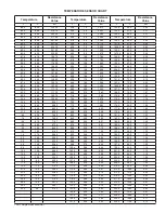
Page 100: ...78 0 1 76 16 6 27 0 95 47 75 2 24 0 10 38 174 2 79 0 1 71 14 8 26 0 90 80 77 0 25 0 10 00 176 0 80 0 1 66 13 0 25 0 86 39 78 0 26 0 9 63 177 8 81 0 1 62 11 2 24 0 82 22 80 6 27 0 9 28 179 6 82 0 1 57...

Page 101: ...101 dap4 User Manual...

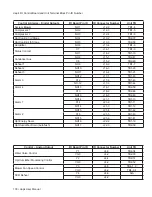
Page 102: ...N A Opt Chilled Water Temperature NTC U10 J20 5 N A NTC GND J20 6 N A Alarms Digital Inputs I O Board Pin ID ID Connector Number Unit TB Compressor 1 High Pressure Alarm ID1 J5 1 TB1 25 Compressor 1...

Page 103: ...TB1 7 Reheat 2 NO10 J16 3 TB1 20 Reheat 3 NO11 J16 4 TB1 21 Alarm 3 NO12 J17 1 TB1 45 C12 J17 2 TB1 43 NC 12 J17 3 TB1 44 Alarm 4 NO13 J18 1 TB2 50 C13 J18 2 TB2 48 NO13 J18 3 TB2 49 Alarm 1 NO14 J21...

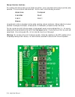
Page 104: ...Simply slide the manual switches to energize the blower compressors humidification reheat and other functions The fan speed of the EC Electronically Commutated motor can be adjusted from 0 10 volts by...

Page 105: ...additional features of Lighting control CO2 level control and Night time temperature and humidity offsets which are explained in this document 1 Two additional sensors can be installed a CO2 sensor C...

Page 106: ...POD will appear on the main screen of dap4 Please contact the Data Aire if your dap4 controller is not set to the gPod model as required b CO2 control settings To access the CO2 level set point press...

Page 107: ...ing a cooling offset or heating offset that cause excessive power consumption and or lead to a system short cycle A warning message will appear under such conditions For instance if cooling offset is...

Page 108: ...will remain off An example of how CO2 is controlled let s assure that the CO2 set point is 1000ppm CO2 dead band is 25ppm Min Valve on is 10 seconds and the Valve PWM is 20 When the CO2 level falls b...

Page 109: ...Set point offsets work as follows Normal daytime mode Cooling and Heating Temp set point Temp set point Humidify and Dehumidify set point Hum set point Temp and Hum set points are adjusted in menu B S...

Page 110: ...com Sales dataaire com Fax 714 921 6010 Main 714 921 6011 Engineering 714 921 6022 Parts Sales Web Site www dataaire com Job Unit Information Data Aire Job Number __________________________ Serial Nu...

Page 111: ...111 dap4 User Manual...

Page 112: ...ange CA 92865 800 347 2473 www dataaire com sales dataaire com ISO 9001 2008 Certified Copyright 2016 Data Aire Inc A member of the CS Group of Companies Creating Products That Make Building Better da...

Reviews: