background image

dCS Scarlatti DAC

 User Manual 

Software Issue 1.2x 


August 2011 


Flename: Scarlatti DAC Manual v1_2x.docx 

Page 17

 English 

version


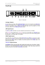
 Word Clock Input / Output 

The 

WCLK In

 connector (R) will accept standard word clock from the source equipment or a master 

clock at 32, 44.1, 48, 88.2, 96, 176.4 or 192kHz. The clock frequency 

MUST

 be an exact multiple of 

the data rate, otherwise the system will not lock. Use the 

Sync

 button to lock the DAC to the external 

word clock. Note that the source 

MUST

 be locked to the same clock, otherwise the system will not be 

locked and periodic clicks will be heard on the outputs. 

When the unit is set to Master mode, the DAC uses its internal clock instead of locking to the data or 

WCLK In

put, and the 

WCLK Out

 connector (S) carries a 44.1kHz word clock. This 

MUST

 be 

connected to the source equipment, so that the system can lock.  

Word clock is used for synchronisation only, it does not carry digital data. 


1394

 Interface 

The IEEE 1394 interface (T) will accept encrypted DSD data from the 

Scarlatti

 Transport or 

Upsampler, as well as from other 

dCS

 transports and upsamplers that are loaded with current 

software. 1394 interfaces are great for carrying lots of digital data - but are very poor at transmitting a 
stable clock, so a separate Word Clock connection is required. The two 1394 ports are identical – they 
can be used as data inputs or as a loop-through. Note that the 1394 bus must not be connected in a 
loop as this will prevent the system initialising.  


SUC

 Connector 

The 

SUC

 connector (U) is an RS232 interface, primarily used to remotely control the unit during 

automated testing. Please contact 

dCS

 for advice on using this interface with a household automation 

system. Note that we recommend using infra-red remote control instead. 

 Mains inlet 

Power is connected via a standard IEC320 connector (V), protected by a fuse (W) and isolated by a 2-
pole power switch (X). 


Summary of Contents for DCS SCARLATTI DAC

Page 1: ...any form or by any means electronic mechanical photocopying recording or otherwise without the prior written permission of dCS1 Any person who does any unauthorised act in relation to this publication may be liable to criminal prosecution and civil claims for damages Information contained in this manual is subject to change without notice and whilst it is checked for accuracy no liabilities can be...

Page 2: ...dCS Scarlatti DAC User Manual Software Issue 1 2x August 2011 Flename Scarlatti DAC Manual v1_2x docx Page 2 English version ...

Page 3: ...sing a Sync Mode 10 Using the DAC in Master Mode 10 Using a Master Clock 11 Front Panel 12 POWER Button 12 DISPLAY Button 12 SYNC Button 13 FILTER Button 13 INPUT button 15 Display 15 MUTE Button 15 MENU Button 15 Remote Control Receiver 15 Rotary Control 15 Rear Panel 16 Analogue Outputs 16 AES Digital Inputs 16 SPDIF Digital Inputs 16 DSD SDIF Digital Interface 16 Word Clock Input Output 17 1394...

Page 4: ...r cable 1394 cable BNC cable 2 spare fuses Notify your dealer as soon as possible if anything is missing or damaged We suggest that you retain the original packaging for possible future use If this is not possible replacement packaging can be ordered from dCS or our distributors Details can be found on our web site at www dcsltd co uk The Scarlatti Transport is supplied with a programmed Nevo S70 ...

Page 5: ... mains supply The unit s voltage setting is shown on the serial number label If this does not match your local supply voltage DO NOT attempt to use the unit Contact your dealer to have the unit reset Using the unit with the wrong mains setting for your local supply may result in serious damage to the unit and will invalidate the warranty Do not attempt to reset the voltage yourself We do not recom...

Page 6: ...le provided with the unit For analogue outputs use with screened cables of the correct type for balanced outputs use screened twisted pair cables fitted with one male XLR connector and one female XLR connector for unbalanced outputs use coax cables fitted with RCA Phono plugs Connect the power cable supplied to the power inlet on the DAC rear panel plug the other end into a convenient power outlet...

Page 7: ... cable Press the Input button repeatedly until your chosen input is displayed This will be either AES1 AES2 RCA1 RCA2 Toslink or BNC The DAC will lock to the source displaying in sequence 44 1k Locking 16 44 1 for example if the source is a CD player Connecting to a Dual AES Source Check that your source equipment is capable of Dual AES operation Connect the AES1 or AES A output on your source equ...

Page 8: ...ing a power amplifier directly Turn the DAC rotary control counter clockwise to set the Volume to minimum 60 0dB on the display Connect either the balanced XLR connectors or unbalanced RCA phono connectors outputs on the DAC rear panel to matching inputs on your power amplifier Switch on the power amplifier Turn the DAC rotary control slowly clockwise until the music is at the right level Play a d...

Page 9: ...ort For this reason we recommend the 2V setting if a preamplifier is used Similarly if you are driving a power amplifier directly and the DAC Volume setting for a comfortable listening level is higher than 10 0 or lower than 20 0 try changing the Output Level setting Press the Menu button press the button once then the Menu button again to display the DAC Settings menu Press the button a few times...

Page 10: ... to a 44 1kHz word clock and the DAC is receiving data at 44 1 88 2 or 176 4kS s or DSD If the system is not set up correctly and fails to lock you will hear clicks noises from the speakers and the signal may be distorted Connect the equipment as shown taking special care to connect the clock cable correctly ANALOGUE OUTPUTS LEFT RIGHT RIGHT LEFT AES 1 AES 2 RCA 1 RCA 2 SPDIF DIGITAL INPUTS TOSLIN...

Page 11: ...ti DAC L L R R Balanced or Unbalanced Analogue Outputs To pre or power amplifier inputs DIGITAL OUTPUTS AES 1 RCA BNC TOSLINK CH1 CH2 SUC 1394 IN WORDCLOCK OUT SDIF AES 2 Figure 3 Using the Scarlatti Transport DAC and Clock together Connect one of the Clock s Word Clock Outputs to the Word Clock Inputs of the Transport and DAC Use the Clock s Frequency button to set the outputs to 44 1kHz to suit ...

Page 12: ...control To set the unit to sleep mode press the POWER button once The main display will turn off the LED over the button will light and the analogue outputs will mute but the unit will remain close to running temperature Press again to return to normal operation To switch off hold down the POWER button for about 5 seconds until Power Down appears on the display then release it When the menu is ope...

Page 13: ...preference and is best done by ear The choice of filter may depend on the type of music you are listening to In PCM mode the first 4 filters give different trade offs between the Nyquist image rejection and the phase response Filter 1 has the best rejection of unwanted Nyquist images and the sharpest roll off resulting in the poorest transient response of the four Filters 2 3 and 4 have progressiv...

Page 14: ...dCS Scarlatti DAC User Manual Software Issue 1 2x August 2011 Flename Scarlatti DAC Manual v1_2x docx Page 14 English version ...

Page 15: ...24 192 or DSD Between tracks on a CD the number of active bits is zero so 0 44 1 may be displayed The icons at the bottom left corner are the Sync mode slave to Audio is shown and the selected Filter Filter 2 is shown The Phase icon appears here if set to inverted The staircase icon gives a visual indication of the Volume or Balance setting with the setting shown in text as well 0 0dB is shown Det...

Page 16: ...mple rates up to 192kS s If the Dual AES menu page is set to On or Auto they can be used together as a Dual AES pair at 88 2 96 176 4 or 192kS s For Dual AES mode to work correctly the source must actually generate Dual AES data not just single AES on 2 connectors SPDIF Digital Inputs The unit features 3 co ax SPDIF inputs labelled RCA1 RCA2 N and BNC P as well as an optical SPDIF input on a Tosli...

Page 17: ...an lock Word clock is used for synchronisation only it does not carry digital data 1394 Interface The IEEE 1394 interface T will accept encrypted DSD data from the Scarlatti Transport or Upsampler as well as from other dCS transports and upsamplers that are loaded with current software 1394 interfaces are great for carrying lots of digital data but are very poor at transmitting a stable clock so a...

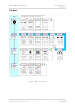
Page 18: ...dCS Scarlatti DAC User Manual Software Issue 1 2x August 2011 Flename Scarlatti DAC Manual v1_2x docx Page 18 English version THE MENU Figure 6 The menu sequence ...

Page 19: ... Menu Guide sheet to help you find the right menu Each unit in the range has either three or four top level menu pages The INFORMATION menu gives software issues serial number contact details and unit set up details Each model has a different SETTINGS menu which allows you to set some features that are not directly accessible from the front panel The DISPLAY SETTINGS menu is used to adjust and tes...

Page 20: ...r help first The DAC Information page displays the unit status Input selected to 1394 nodes connected Sync to Audio WClk Master Unlocked Locked at kS s Input is PCM DSD No De Emphasis De Emphasis is Filter Phase Normal Inverted Internal temperature C Use the rotary control to scroll down the list and press the MENU button to exit The CD Update feature allows you to load new software into your syst...

Page 21: ... the format flags in the digital data and automatically sets the AES1 2 inputs to Single AES or Dual AES mode as required This is the usual setting Note that if the format flag in the data is wrong you will need to manually select the correct setting Off Dual AES mode is disabled On Dual AES mode can be manually selected using the INPUT button or the remote control Sets the Output Level to 2V rms ...

Page 22: ...ight If the these are the wrong way around the left and right channels are swapped somewhere in your system Runs a Phase Check routine to test the system for phase reversals Noise is output in phase on both channels while the display shows In Phase Press the MENU button the noise on the right channel is inverted while the display shows Out of Phase The first burst should produce a central image th...

Page 23: ...put on 1x BNC connector In Master mode a TTL compatible 44 1kHz word clock appears on this output not temperature compensated Frequency response set to Filter 1 Fs 32kS s Fs 44 1 or 48kS s Fs 88 2 or 96kS s Fs 176 4 or 192kS s DSD 0 1 0 5dB 10Hz to 15kHz 0 1dB 10Hz to 20kHz 0 1dB 10Hz to 20kHz 0 1dB 10Hz to 20kHz 0 1dB 10Hz to 20kHz 3dB 38kHz 3dB 67kHz 3dB 66kHz Residual noise Better than 110dB0 2...

Page 24: ...could result in damage to the unit risk of fire or electric shock and will invalidate the warranty Referring to the diagram below remove the power cable use a small flat bladed screwdriver to pry up the tab on the fuse carrier A and pull it out Push the blown fuse out of the clip in the carrier B and dispose of it Fit a new fuse in the clip C and push the carrier back into the unit so that it clic...

Page 25: ...e product is operated without a mains earth or ground connection the unit is returned inadequately packed dCS reserve the right to apply a service charge if a product returned for warranty repair is found to be operating correctly or if a product is returned without a returns number being issued This warranty covers parts and labour only it does not cover shipping charges or tax duty Our dealers o...

Page 26: ...ecessary also to increase the capacity of the electronics add extra connectors or extra front panel controls Please note that not all software updates make an earth shattering change You should have a clear idea of what you expect to gain before updating to the latest issue We recommend that you keep your software up to date Check the dCS web site for the latest software updates Before requesting ...

Reviews: