dCS Vivaldi DAC
User Manual
Software Issue 1.0x
August 2012
Filename: Vivaldi DAC Manual v1_0x.docx
Page 23
English
version
When the unit is set to Master mode, the DAC uses its internal clock instead of locking to the data or
one of the
Word Clock In
puts, then the
Word Clock Out
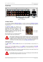
connector (S) carries a 44.1kHz word clock.
This
MUST
be connected to the source equipment, so that the system can lock.
Word clock is used for synchronisation only, it does not carry digital data.
Test
interface
The
Test
interface (U) is an RS232 interface two modes, set by the
Settings > RS232
menu page.
•
B
inary mode is used to remotely control the unit during automated production testing at
dCS
.
•
T
ext mode is for use with a household automation system. If you would like to use this mode,
please download the list of remote control commands from
.
The interface is designed to be used with a “straight through” cable, wired pin 1 to pin 1, etc.
The pin connections are:
•
Pin 2 –
dCS
unit transmit
•
Pin 3 –
dCS
unit receive
•
Pin 5 – ground
•
Shell – cable screen & drain wire
We recommend using infra-red remote control instead.
Mains inlet
Power is connected via a standard IEC320 connector (V), protected by a fuse and isolated by a 2-pole
power switch.
Label
The label (W) states the unit’s serial number and the nominal voltage to which the unit is set. It is
important to quote the serial number if you need assistance.

