Display User Manual
DDJ07310001
1-Oct-03
Page 4
2
Hardware
2.1
Unpacking
Carefully remove the items from their package and store the packaging safely. After unpacking,
inspect the contents for any damage that may have occurred during shipment. In the event of
damage, refer to the '
Technical Support'
section of this manual.
2.2
Installation
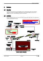
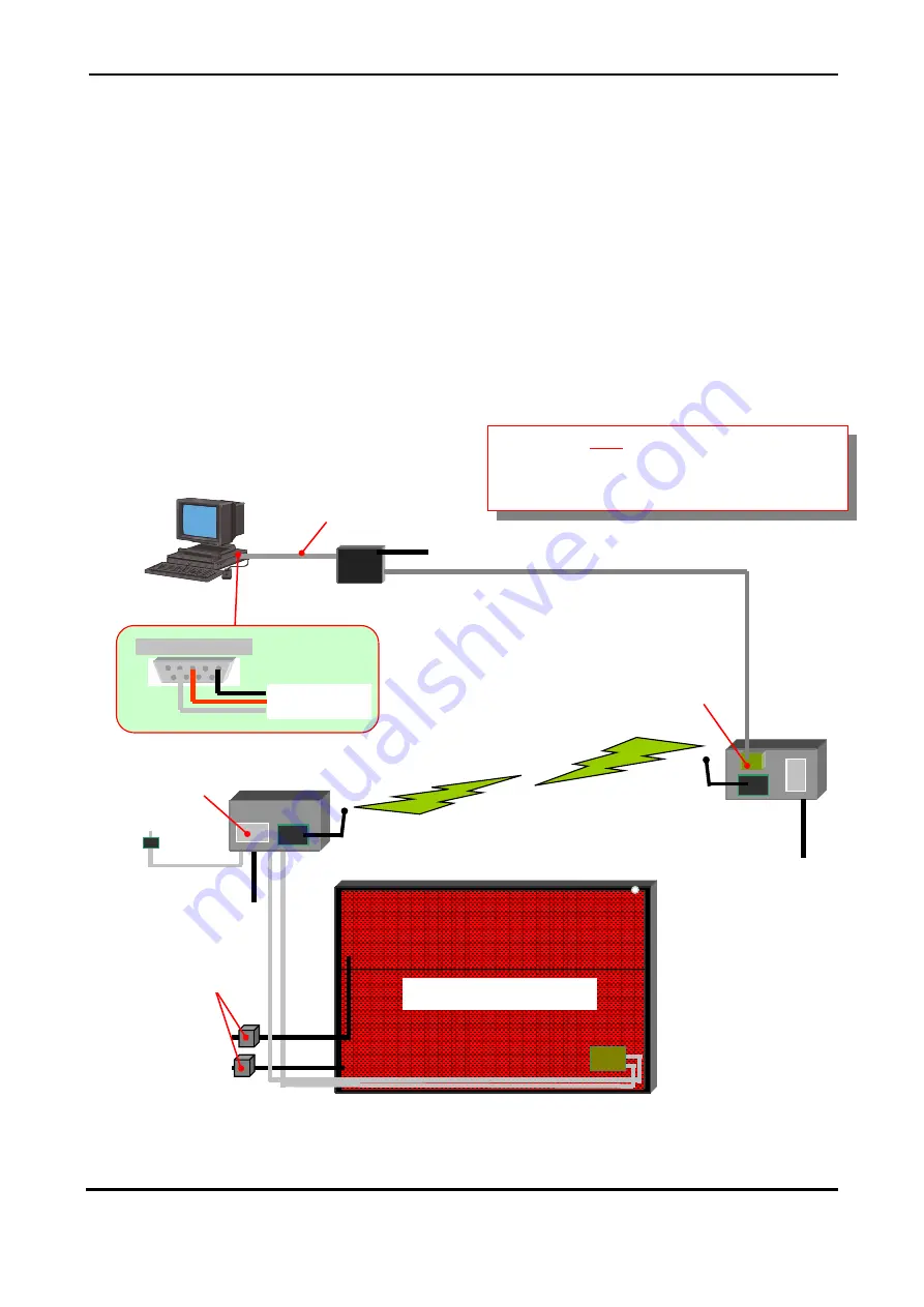
Mount the Displays securely and connect the cables as shown in the Figure below. The Light Sensor
is fitted in the top right-hand corner.
Figure 2.1 – System Configuration
Wireless Modem
TX
TX Control Box
Graphic Board Display
64 x 120 Pixels
RX Control Box
Warning: Do NOT power up the Display Board
until all cabling is connected.
Power Consumption per Display: 2500W. Two
120V AC Mains required per Display.
Control PC with
GRAFIT software
RS232 Serial Cable, 9-way
to 5 Pin Maplin
9-way wiring at PC
Pin 5 = GND (Black)
Pin 3 = Rx (Red)
Pin 2 = Tx (White)
RS485 Box
RS485 Cable
RS485 Card converts the
RS485 signal to RS232 for
Modem
Wireless Modem
RX
120V AC Power
120V AC Power
Light Sensor
Location of Logic
Board
Temp Probe
External Isolators
provided by the
Customer
7.5V PSU
120V AC Power
120V AC Power
120V AC Power


