Display User Manual
DDJ07310001
1-Oct-03
Page 5
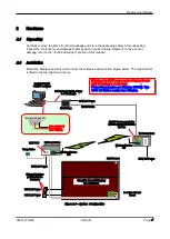
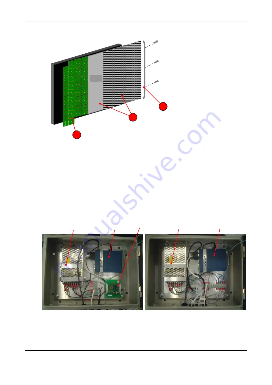
Figure 2.2 – Access to Parts.
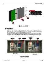
2.3 Control Boxes
There are two Control Boxes supplied with the Displays. The TX Control Box houses the Transmit
Wireless Modem, a 7.5 PSU and the RS485 Card to convert the RS485 signal back to RS232. The
RX Control Box houses the Receive Wireless Modem, and a 7.5 PSU.
Located on the bottom of the Boxes are cable glands through which the incoming 120V AC power
and Serial Cables for the Modems are routed. The two Temp Signal cables and two RS232 Serial
Cables to the each Displays Logic Board are also routed out of the RX Control Box.
Figure 2.3 – Control Boxes.
TX Control Box
1
INSTRUCTIONS
1. Unscrew the 3 screws at the right-
hand side and remove Side Profile.
Put all hardware in a safe place.
2. Slide out Visor and Lens carefully.
3. Remove Display Panels as required.
RS485 Card
Modem
7.5V PSU for
Modem
RX Control Box
Lens
3
1
2
Modem
7.5V PSU for
Modem


