Display User Manual
DDJ07310001
1-Oct-03
Page 8
2.6 Logic Board, PAS145
The PAS145 Board consists of a V53 Micro Processor running at 29 MHz. (bus speed 14.5 MHz.)
and associated peripheral devices together with the following features necessary to control and
monitor the Display System as a whole:
- Real Time Clock if required.
- RS485 optically isolated 4 wire communications interface for communication with the rest
of the Passenger Information Display System.
- Program memory to store the application code which the Logic Board executes in order to
allow the Display to operate.
- SRAM (896 Kbytes) memory to store various program variables and show data.
- 2 display/control interfaces to facilitate connection with the Display Boards, one for each
side of a double-sided Display (largest Display requirement).
- Serial EEPROM (4 Kbytes) for reset determination purposes and in-house usage where
required.
- Flash memory
This device provides for 512KB of non-volatile memory but has the facility to be erased and
reprogrammed on-board.
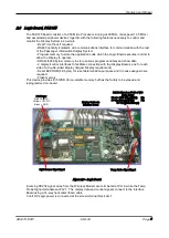
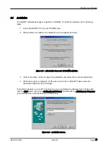
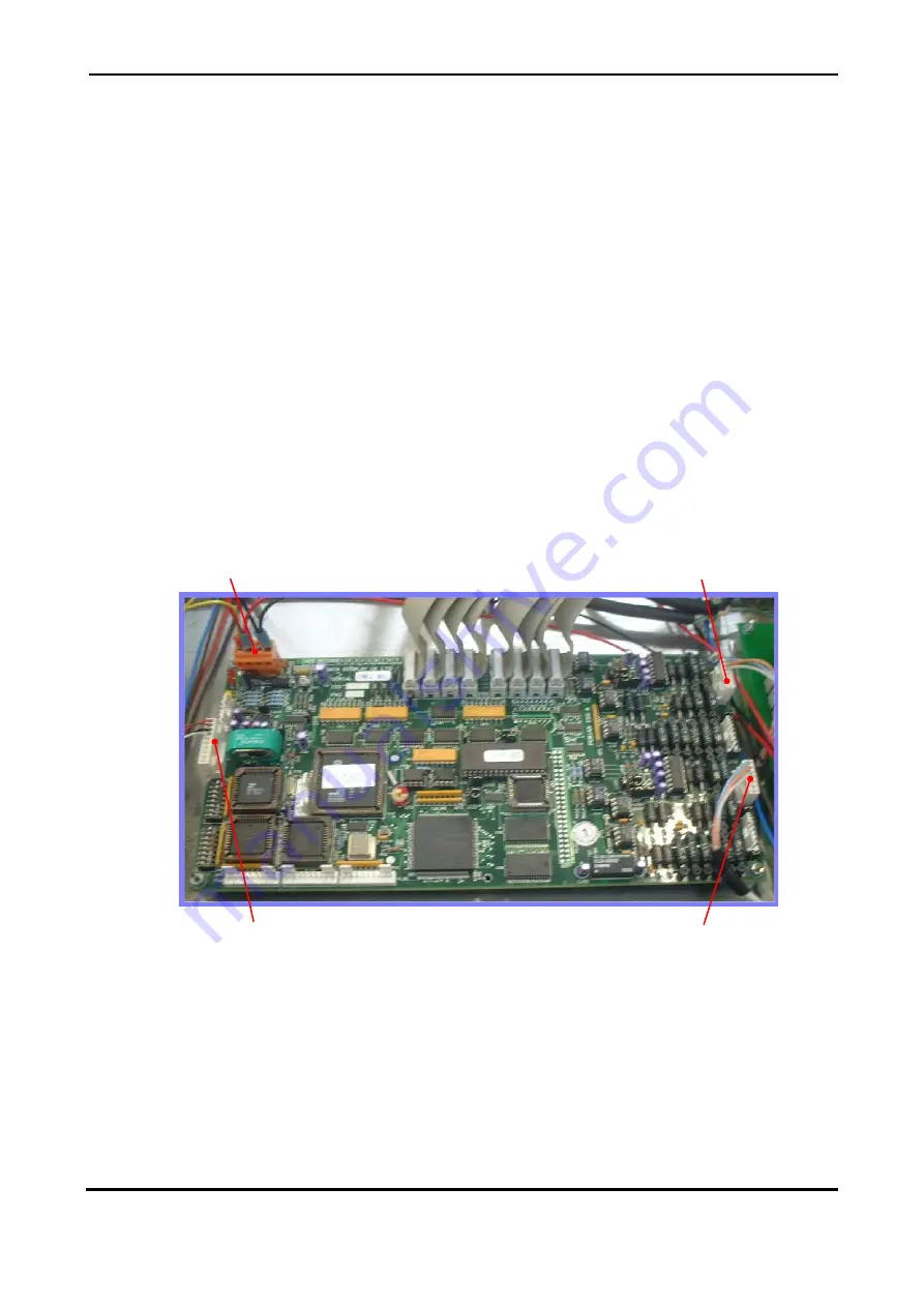
Figure 2.6 – Logic Board.
Incoming RS232 signal wires from the Wireless Modem are terminated at PL18, while the Temp
Probe Signal terminates at PL21. The display data and control signals connect to the Interface
Board using a 14-way horizontal ribbon cable.
5 Volt DC Logic power is connected at the screw terminal block at J1.
Temp Probe Signal Input
Light Sensor Signal Input
DC Power
Red = 5V DC
Yellow = 15V DC
Black = GND
Display Cables to
Interface Board
RS232 Signal on PL18 of V53
Logic Board
Pin 1 = GND (Blue/White) Pin
2 = Rx (Orange/White) Pin
3 = Tx (White/Orange)


