Setting Up and Installing a SCSI Bus
4-10
014–002091
Installing a SCSI Bus and SCSI Devices
This section outlines the followingsteps to physically install a SCSI bus on your
system:
•
Installingconfiguration jumpers on each external SCSI tape and/or disk drive
•
Connectingthe SCSI bus cable in a daisy-chain to the subsystems and
stand-alone devices
•
Terminatinga SCSI bus
To perform each step, you will need the device- and subsystem-specific
documentation listed in
Guide to AViiON
and DG/UX
System Documentation
for
each bus component.
The next section in this chapter describes how to connect an external SCSI bus to your
computer unit.
Before you begin physically installing your SCSI bus and SCSI devices, plan your
cablingscheme(s) and assign SCSI ID numbers to each device accordingto the rules
described in the precedingsections of this chapter. Make certain to assign ID numbers
compatible with any application software requirements planned for your system.
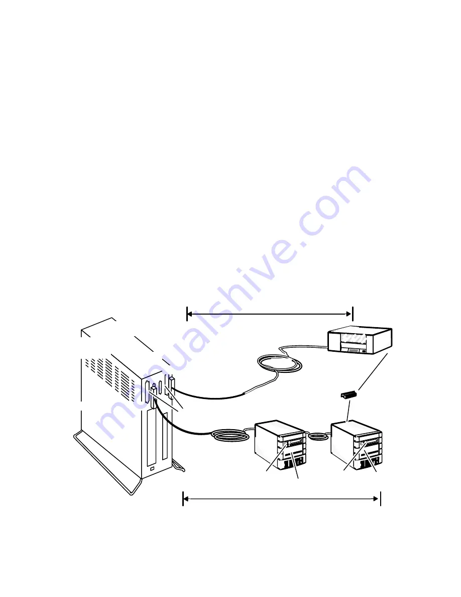
Figure 4Ć6 shows a sample AViiON 530 and 4600 series SCSI layout that adheres to
SCSI bus cable and device identification rules.
Stand–alone
tape drive
SCSI ID 5
Tape drive
SCSI ID 5
Disk drive
SCSI ID 0
Disk drive
SCSI ID 1
Diskette
drive
SCSI ID 3
Disk drive
SCSI ID 0
Tape drive
SCSI ID 4
Tape drive
SCSI ID 4
SCSI A bus 14.85 ft max.
Bus
terminator
Rear panel
connector(s)
SCSI B bus 18.6 ft max.
4.75 ft. internal bus cable
10 ft.
1.3 ft.
5 ft.
1 ft. internal bus cable
Figure 4-6 SCSI Cable Rules and Sample Device IDs
Summary of Contents for AViiON 4600 Series
Page 1: ... Customer Documentation P R O D U C T L I N E ...
Page 2: ......
Page 6: ......
Page 14: ...Preface xii 014 002091 ...
Page 24: ...Contents xxii 014 002091 ...
Page 58: ...Setting Up Your Computer System 2 18 014 002091 ...
Page 84: ...Setting Up and Installing a SCSI Bus 4 16 014 002091 ...
Page 122: ...Expanding and Maintaining Your Computer System 6 18 014 002091 ...
Page 148: ...Adding or Replacing Memory Modules 8 8 014 002091 ...
Page 182: ...Replacing the System Board 10 12 014 002091 ...
Page 188: ...Replacing the Fan Assembly 11 6 014 002091 ...
Page 236: ...Using the System Control Monitor B 22 014 002091 ...
Page 248: ...Solving Power Up Problems C 12 014 002091 ...
Page 260: ...Index 12 014 002091 ...
Page 262: ......
Page 266: ...Appendix Title 093 xxxxxx 2 Licensed Material Property of Data General Corporation ...


