Setting Up and Installing a SCSI Bus
014–002091
4-13
Connecting an External SCSI Bus to the
Computer Unit Rear Panel
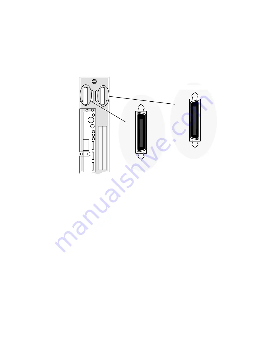
Figure 4Ć7 shows the location of the SCSI connectors on the rear panel of your
computer.
Computer Unit
Rear Panel
For I/O expansion
board (Optional)
A
SCSI
B
First SCSI connector
SCSI
Second SCSI connector
(optional)
NOTE:
If your system does not include an I/O expansion board, the rear panel slot
marked “SCSI B” will not contain a connector.
Figure 4-7 AViiON 530 and 4600 Series External SCSI Connectors
After
you verify that the cable lengths and SCSI IDs in your configuration adhere to
the rules listed earlier in this chapter, follow these steps to connect an external SCSI
bus to the rear panel of your computer:
1.
Turn off the power to your computer, subsystems, and peripherals before
connecting the SCSI bus.
2.
If present, remove the SCSI bus terminator plug from the rear panel connector
as shown in Figure 4Ć8. Simply open the spring clips by pushing them vertically,
and then pull the plug off.
Summary of Contents for AViiON 4600 Series
Page 1: ... Customer Documentation P R O D U C T L I N E ...
Page 2: ......
Page 6: ......
Page 14: ...Preface xii 014 002091 ...
Page 24: ...Contents xxii 014 002091 ...
Page 58: ...Setting Up Your Computer System 2 18 014 002091 ...
Page 84: ...Setting Up and Installing a SCSI Bus 4 16 014 002091 ...
Page 122: ...Expanding and Maintaining Your Computer System 6 18 014 002091 ...
Page 148: ...Adding or Replacing Memory Modules 8 8 014 002091 ...
Page 182: ...Replacing the System Board 10 12 014 002091 ...
Page 188: ...Replacing the Fan Assembly 11 6 014 002091 ...
Page 236: ...Using the System Control Monitor B 22 014 002091 ...
Page 248: ...Solving Power Up Problems C 12 014 002091 ...
Page 260: ...Index 12 014 002091 ...
Page 262: ......
Page 266: ...Appendix Title 093 xxxxxx 2 Licensed Material Property of Data General Corporation ...


