


Connecting External Devices to VME Option Boards
4-41
014–001867
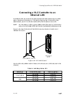
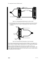
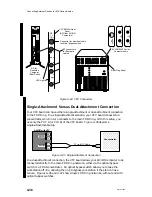
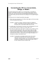
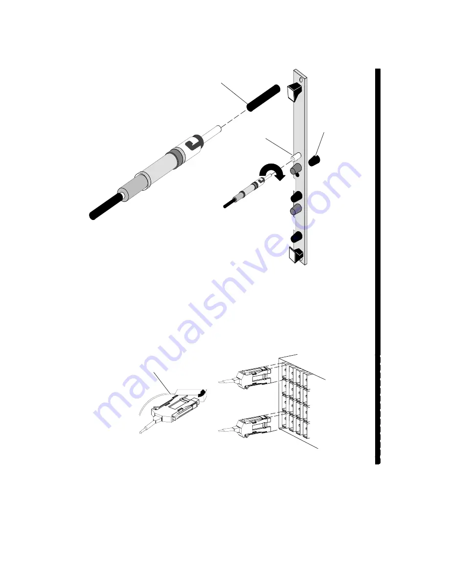
Remove dust caps
Plug bayonet into
ST jack
Remove dust caps
Figure 4–48 Attaching ST Bayonet Connectors to a VFC Connector Jack
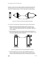
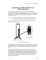
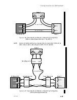
4. Connect the other end(s) of the cable to your second device. Make certain that
physical unit A on your second device connects to PHY B on the VFC, and that
the VFC PHY A connects to physical unit B on your second device.
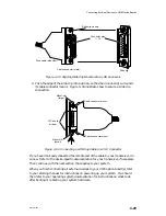
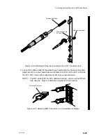
NOTE:
The MIC ends of ST–to–MIC cables are keyed: you can connect them
only one way. Figure 4–49 shows a typical MIC connection.
Remove dust cover
Figure 4–49 Attaching MIC Connectors to a Concentrator or Bridge
Summary of Contents for AViiON 5000 Series
Page 2: ......
Page 6: ......
Page 12: ...Preface x 014 001867 ...
Page 86: ...Configuring VME Option Boards 2 52 014 001867 ...
Page 144: ...Connecting External Devices to VME Option Boards 4 44 014 001867 ...
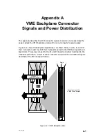
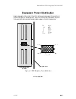
Page 150: ...VME Backplane Connector Signals and Power Distribution A 6 014 001867 ...
Page 196: ...Assigning VME Data Bus and Interrupt Priorities E 10 014 001867 ...
Page 206: ......
Page 210: ...Appendix Title ...


