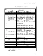
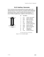

External Device Connector Pin Assignments
C-11
014–001867
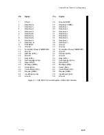
Pin Signal
26
Ground (GND)
27
Data Bus 0 (DB0)–
28
Data Bus 1–
29
Data Bus 2–
30
Data Bus 3–
31
Data Bus 4–
32
Data Bus 5–
33
Data Bus 6–
34
Data Bus 7–
35
Data Bus P–
36
Ground
37
Ground
38
Termination Power (TERMPWR)
39
Ground
40
Attention (ATN)–
41
Ground
42
Busy (BSY)–
43
Acknowledge (ACK)–
44
Reset (RST)–
45
Message (MSG)–
46
Select (SEL)–
47
Control/Data (C/D)–
48
Request (REQ)–
49
Input/Output (I/O)–
50
Ground
Pin Signal
1
Shield
2
Data Bus 0+
3
Data Bus 1+
4
Data Bus 2+
5
Data Bus 3+
6
Data Bus 4+
7
Data Bus 5+
8
Data Bus 6+
9
Data Bus 7+
10
Data Bus P+
11
DIFFSENS
12
Ground
13
Termination Power (TERMPWR)
14
Ground
15
Attention (ATN)+
16
Ground
17
Busy (BSY)+
18
Acknowledge (ACK)+
19
Reset (RST)+
20
Message (MSG)+
21
Select (SEL)+
22
Control/Data (C/D)+
23
Request (REQ)+
24
Input/Output (I/O)+
25
Ground
Figure C–7 VSA SCSI Connector Signals – Differential Interface
Summary of Contents for AViiON 5000 Series
Page 2: ......
Page 6: ......
Page 12: ...Preface x 014 001867 ...
Page 86: ...Configuring VME Option Boards 2 52 014 001867 ...
Page 144: ...Connecting External Devices to VME Option Boards 4 44 014 001867 ...
Page 150: ...VME Backplane Connector Signals and Power Distribution A 6 014 001867 ...
Page 196: ...Assigning VME Data Bus and Interrupt Priorities E 10 014 001867 ...
Page 206: ......
Page 210: ...Appendix Title ...


