


Special Instructions for Model-Specific VME Hardware
D-16
014–001867
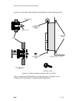
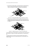
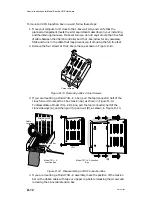
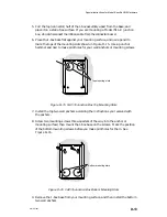
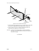
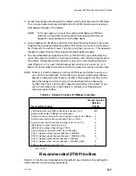
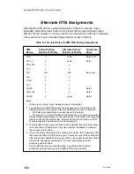
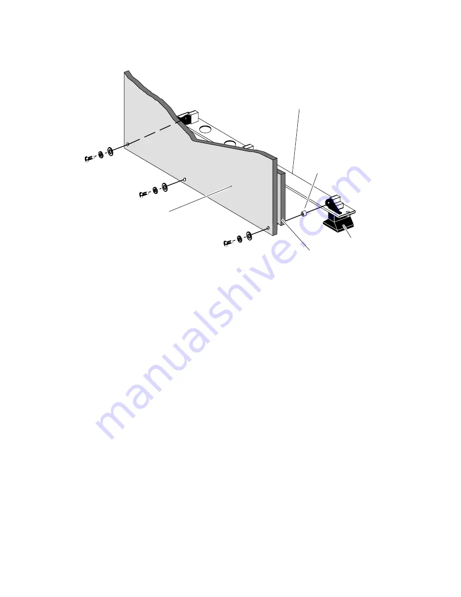
Air dam
VFC board
(solder side)
Ejector
assembly
Ejector spacer
Daughter board
(VFC component side)
Figure D–19 VFC and 6U Air Dam Assembly
3. Place the original board component side up on an antistatic surface. Then, attach
the air dam to the replacement controller board as shown in Figure D–19.
4. Place the original VFC board in the antistatic bag, packing material, and
shipping box that accompanied your replacement board.
CAUTION: Since the VFC three–board assembly is wider than most VMEbus
option boards, you should take particular care when inserting the VFC
into the VME card cage.
End of Appendix
Summary of Contents for AViiON 5000 Series
Page 2: ......
Page 6: ......
Page 12: ...Preface x 014 001867 ...
Page 86: ...Configuring VME Option Boards 2 52 014 001867 ...
Page 144: ...Connecting External Devices to VME Option Boards 4 44 014 001867 ...
Page 150: ...VME Backplane Connector Signals and Power Distribution A 6 014 001867 ...
Page 196: ...Assigning VME Data Bus and Interrupt Priorities E 10 014 001867 ...
Page 206: ......
Page 210: ...Appendix Title ...


