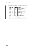


Configuring VME Option Boards
2-44
014–001867
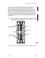
VTRC
P1
P99
P5
P6
P7
P4
P67
P65
P63
P61
P51
P49
P47
P45
P59
P57
P55
P53
P41
P43
P31
P17
P39
P37
P35
P33
P21
P19
P15
P13
P27
P25
P29
P23
P77
P75
P71
P73
P69
P87
P97
P95
P93
P79
P83
P102 P100
P89
P91
P81
P85
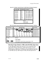
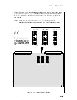
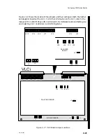
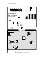
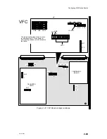
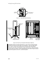
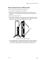
The jumper configuration shown
here is for board position 0 and for
DG/UX revision 5.4.2 or later. To
configure for other board positions
or other operating system revisions,
refer to the tables that follow.
P1
P99
P5
P6
P7
P4
P75
P69
P67
P59
P39
P27
P75
P69
P85
P91
Figure 2–18 VTRC Board Jumper Locations
Summary of Contents for AViiON 5000 Series
Page 2: ......
Page 6: ......
Page 12: ...Preface x 014 001867 ...
Page 86: ...Configuring VME Option Boards 2 52 014 001867 ...
Page 144: ...Connecting External Devices to VME Option Boards 4 44 014 001867 ...
Page 150: ...VME Backplane Connector Signals and Power Distribution A 6 014 001867 ...
Page 196: ...Assigning VME Data Bus and Interrupt Priorities E 10 014 001867 ...
Page 206: ......
Page 210: ...Appendix Title ...


