

Installing and Removing VME Option Boards
3-2
014–001867
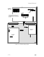
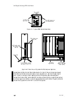
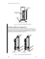
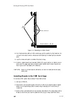
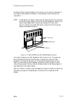
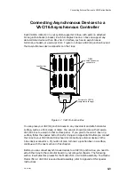
Eurocard 6U
board
J1 and J2 connectors
to VME backplane
Air dam with
ejector handles
Figure 3–1 Typical VME Board Assembly
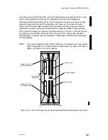
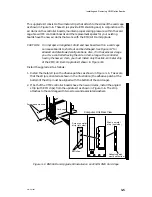
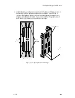
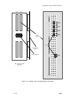
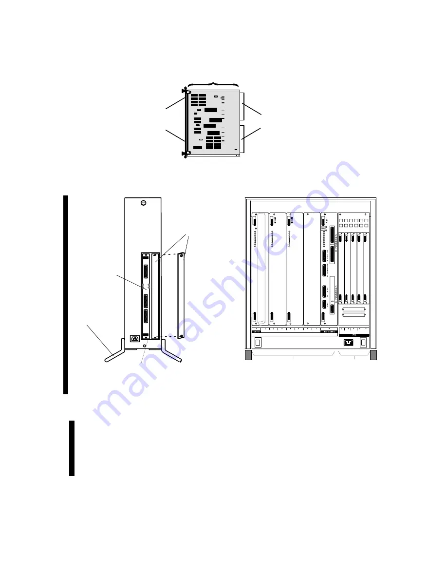
Cover plate over
empty slot
VME option board
connectors and
air dam
Floor stand
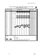
3–Slot VMEbus options
card cage (2 user slots)
6–Slot VMEbus
options card cage
(5 user slots)
Computer
logic section
Figure 3–2 Rear View of Typical AViiON Computer Systems
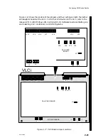
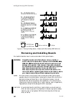
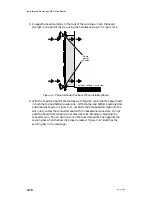
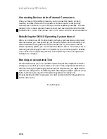
A backplane printed circuit board attaches to the rear of the card cage (as viewed
from the rear of the unit) and contains two connectors (J1 and J2) for each board
slot. Figure 3–3 shows a card cage layout with the guide rails and backplane
connectors for two VME option boards. A system supporting more option boards has
a similar layout, but differs in size of cage, backplane, and number of guide rails and
connectors. Appendix A lists the J1 and J2 bus signals.
Summary of Contents for AViiON 5000 Series
Page 2: ......
Page 6: ......
Page 12: ...Preface x 014 001867 ...
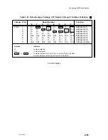
Page 86: ...Configuring VME Option Boards 2 52 014 001867 ...
Page 144: ...Connecting External Devices to VME Option Boards 4 44 014 001867 ...
Page 150: ...VME Backplane Connector Signals and Power Distribution A 6 014 001867 ...
Page 196: ...Assigning VME Data Bus and Interrupt Priorities E 10 014 001867 ...
Page 206: ......
Page 210: ...Appendix Title ...