

Connecting External Devices to VME Option Boards
4-17
014–001867
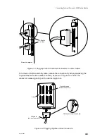
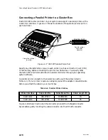
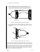
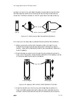
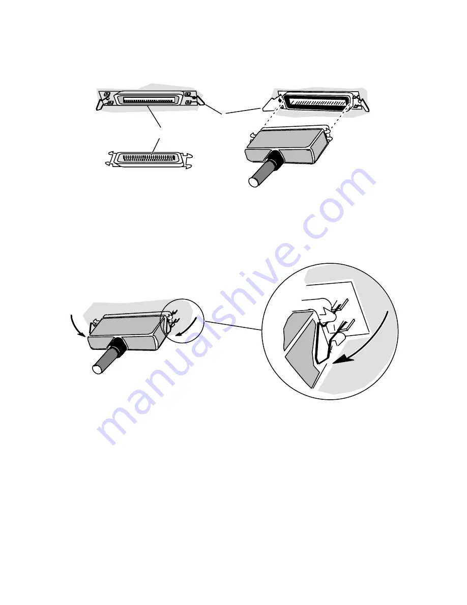
Connector pins
1–36
Printer cable
connector (male)
VDC/8P
(female)
Printer cable
Spring clip
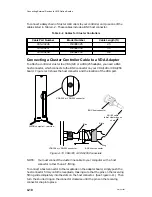
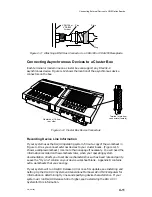
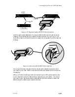
Figure 4–18 Plugging Together VDC/8P Printer Connectors
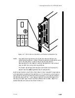
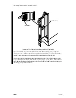
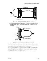
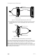
Push the spring clips attached to the top and bottom of the printer port connector
sideways into the brackets on the cable connector as shown in Figure 4–19. Your
horizontal pressure will push the clips into place; do not squeeze or pull the clips out
of shape.
Figure 4–19 Securing the VDC/8P Printer Connector
If you haven’t already connected the remote end of the cable(s) to each printer in
your system, do so now. Refer to the device-specific documentation for each printer,
if necessary.
When you finish connecting all external devices to your VME option board(s), refer
to your starting manual for instructions on powering up your system. You should
then refer to your operating system documentation for instructions on what to do
after booting or rebooting your system hardware.
Summary of Contents for AViiON 5000 Series
Page 2: ......
Page 6: ......
Page 12: ...Preface x 014 001867 ...
Page 86: ...Configuring VME Option Boards 2 52 014 001867 ...
Page 144: ...Connecting External Devices to VME Option Boards 4 44 014 001867 ...
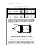
Page 150: ...VME Backplane Connector Signals and Power Distribution A 6 014 001867 ...
Page 196: ...Assigning VME Data Bus and Interrupt Priorities E 10 014 001867 ...
Page 206: ......
Page 210: ...Appendix Title ...


