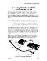


Connecting External Devices to VME Option Boards
4-19
014–001867
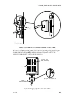
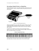
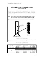
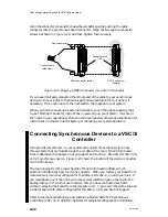
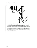
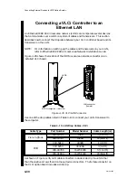
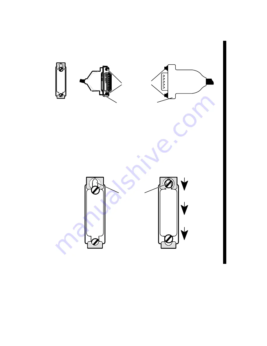
As shown in Figure 4–21, LAN cable connectors include slide clip mounts rather
than the captive screws found on most asynchronous device connectors. The female
connector on the VTC option board includes a slide clip.
Slide clip
Drop cable
Cable connector (male)
Slide clip mounts
Figure 4–21 Connector Slide Clip and Slide Clip Mounts
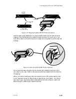
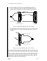
To connect your LAN drop cable to a standard slide clip, follow these directions.
1. Before you connect your first LAN transceiver to the VTC board in your
computer’s card cage, disconnect electrical power to the system. Refer to the
Ethernet/IEEE 802.3 Local Area Network Installation Guide if necessary.
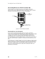
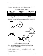
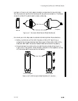
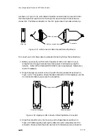
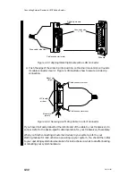
2. Align the larger mount slot on the clip with the screw behind it as shown in
Figure 4–22. This position allows the cable connector to fit completely over the
VTC connector before you secure the connection.
Slide clip misaligned
Large clip slot
Slide clip aligned
Figure 4–22 LAN Connector Slide Clip Before Connection
Summary of Contents for AViiON 5000 Series
Page 2: ......
Page 6: ......
Page 12: ...Preface x 014 001867 ...
Page 86: ...Configuring VME Option Boards 2 52 014 001867 ...
Page 144: ...Connecting External Devices to VME Option Boards 4 44 014 001867 ...
Page 150: ...VME Backplane Connector Signals and Power Distribution A 6 014 001867 ...
Page 196: ...Assigning VME Data Bus and Interrupt Priorities E 10 014 001867 ...
Page 206: ......
Page 210: ...Appendix Title ...


