
Special Instructions for Model-Specific VME Hardware
D-6
014–001867
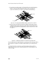
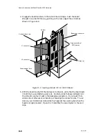
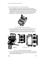
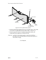
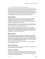
3. Plug each 64-pin cable connector into the connectors on the VAC/16 board, as
shown in Figure D–6. (Note the position of the J1 and J2 connectors in
Figure D–6; the VAC/16 in the figure is reversed for ease of assembly.)
J2 connector
J1 connector
Figure D–6 Connecting External Ribbon Cable to a Model 7411–K VAC/16
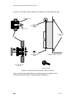
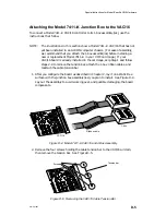
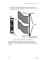
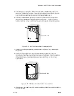
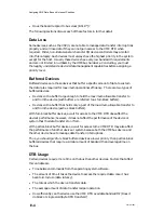
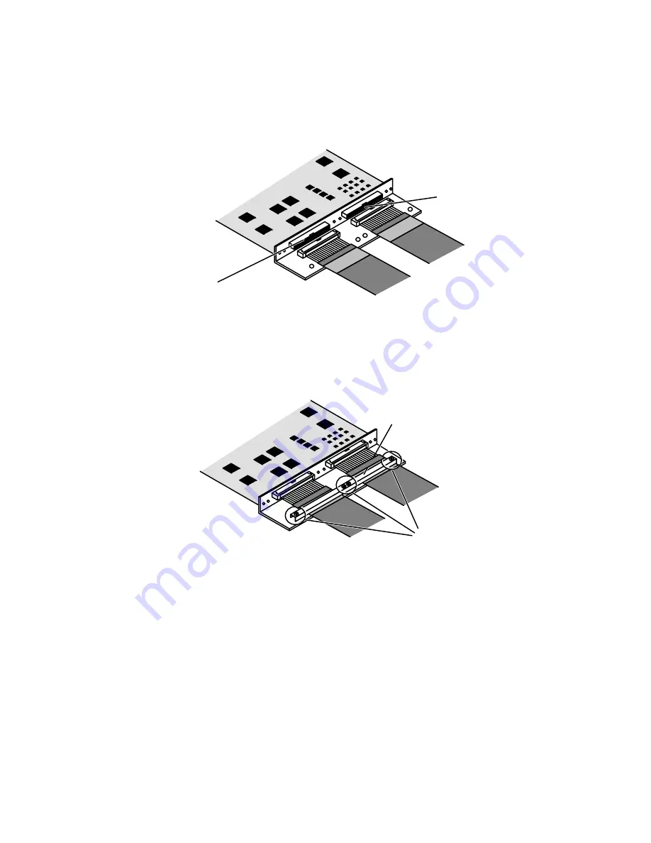
4. After you firmly seat the 64-pin connector, reattach the cable tension bar by
installing and securing the four screws. Make certain the connectors are not
strained by the weight of the cable(s) before you secure the tension bar. Refer
to Figure D–7.
Tension bar
Screws
Figure D–7 Attaching the Model 7411–K VAC/16 Cable Tension Bar
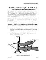
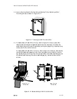
If your VAC/16 board is already installed in a preconfigured VME card cage, refer to
the instructions in Chapter 4 to connect external devices to your VAC/16 junction
box.
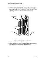
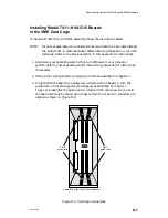
To install a Model 7411–K VAC/16 in your VME card cage, continue with the
instructions in the next section, “Installing Model 7411–K VAC/16 Boards in the
VME Card Cage.”
Summary of Contents for AViiON 5000 Series
Page 2: ......
Page 6: ......
Page 12: ...Preface x 014 001867 ...
Page 86: ...Configuring VME Option Boards 2 52 014 001867 ...
Page 144: ...Connecting External Devices to VME Option Boards 4 44 014 001867 ...
Page 150: ...VME Backplane Connector Signals and Power Distribution A 6 014 001867 ...
Page 196: ...Assigning VME Data Bus and Interrupt Priorities E 10 014 001867 ...
Page 206: ......
Page 210: ...Appendix Title ...


