

Special Instructions for Model-Specific VME Hardware
D-9
014–001867
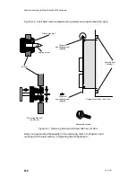
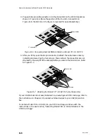
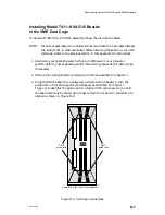
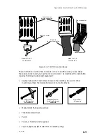
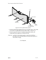
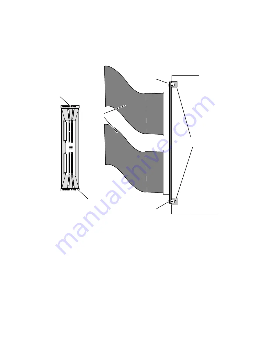
6. Once the board is seated in the card cage slot, secure the board in place by
installing the air dam screws, together with any washers you removed, into the
securing bar, as shown in Figure D–10.
Card cage rear
view
Securing screws
and washers
(Phillips or flat)
Securing bar
Securing bar
Securing bars
(internal)
Cable to
J-box(es)
Securing screws
and washers
(Phillips or flat)
Computer chassis — side view
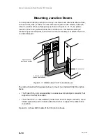
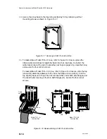
Figure D–10 Securing a VAC/16 Board in the Card Cage
When you finish securing the VAC/16 to the card cage securing bars, return to
Chapter 3 and continue with the last section in that chapter, “Completing the
Configuration,” before connecting external devices to your J-box(es), as described in
Chapter 4.
Summary of Contents for AViiON 5000 Series
Page 2: ......
Page 6: ......
Page 12: ...Preface x 014 001867 ...
Page 86: ...Configuring VME Option Boards 2 52 014 001867 ...
Page 144: ...Connecting External Devices to VME Option Boards 4 44 014 001867 ...
Page 150: ...VME Backplane Connector Signals and Power Distribution A 6 014 001867 ...
Page 196: ...Assigning VME Data Bus and Interrupt Priorities E 10 014 001867 ...
Page 206: ......
Page 210: ...Appendix Title ...


