


Special Instructions for Model-Specific VME Hardware
D-11
014–001867
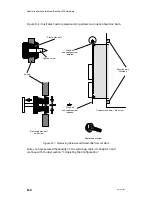
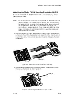
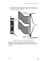
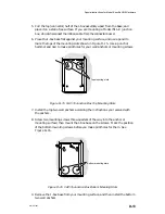
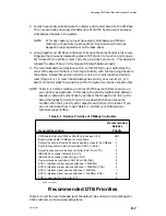
5-ft cable
to rear of computer
Asynchronous
device connectors
Cable connector
Cable tension bar
Cable connector
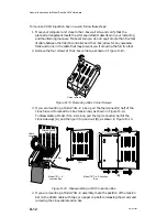
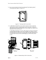
Model 7411–KA
Junction Box
Model 7411–K
Junction Box
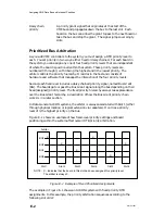
Figure D–12 VAC/16 Junction Boxes
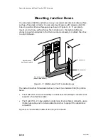
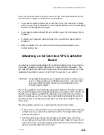
These instructions outline how to mount a J-box to an office wall; you can adapt
these procedures to suit your particular environment. As described, the installation
requires the following tools and equipment:
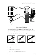
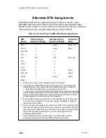
•
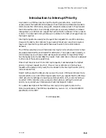
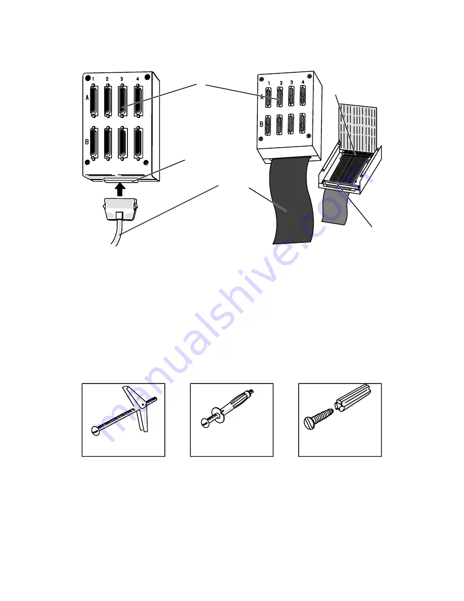
Appropriate anchors and screws to secure the assembly to a wall or other
mounting surface; the devices below work on most surfaces.
Toggle bolt—
for wall paneling
and wallboard
Vinyl insert—
for masonry
Expanding insert—
for wall paneling and
wallboard
•
Medium (#2) Phillips screwdriver.
•
Flat-blade screwdriver.
•
Pencil.
•
Punch, or hammer and large nail.
•
Tape or paper clip (for Model 7411–K assembly only).
Summary of Contents for AViiON 5000 Series
Page 2: ......
Page 6: ......
Page 12: ...Preface x 014 001867 ...
Page 86: ...Configuring VME Option Boards 2 52 014 001867 ...
Page 144: ...Connecting External Devices to VME Option Boards 4 44 014 001867 ...
Page 150: ...VME Backplane Connector Signals and Power Distribution A 6 014 001867 ...
Page 196: ...Assigning VME Data Bus and Interrupt Priorities E 10 014 001867 ...
Page 206: ......
Page 210: ...Appendix Title ...


