


Special Instructions for Model-Specific VME Hardware
D-13
014–001867
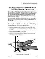
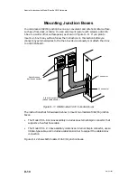
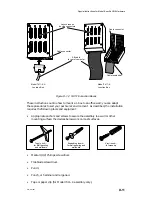
5. Pull the top (connector) half of the J-box assembly apart from the base, and
place it on a static-free surface. If you are mounting a Model 7411–K junction
box, do not disconnect the ribbon cable from the connector board.
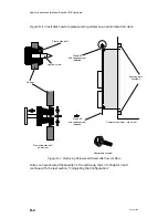
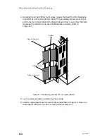
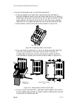
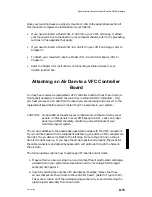
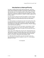
6. Place the J-box base flat against your mounting surface, and use a pencil to
mark the tops of the mounting slots shown in Figure D–15. Use a punch or
hammer and nail to make pilot holes for your wall anchors or mounting screws.
Top mounting slots
Figure D–15 VAC/16 Junction Box Top Mounting Slots
7. Install the top two wall anchors according the instructions you received with
the anchors.
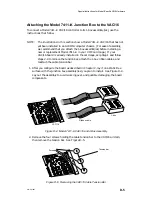
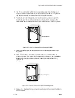
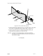
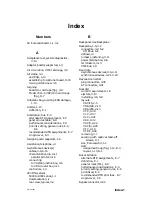
8. Screw two mounting screws three-quarters of the way into the anchor or
mounting surface; then mount the J-box base on the screws. Mark the position
of the bottom mounting screws before you make pilot holes for them. See
Figure D–16.
Bottom mounting slots
Figure D–16 VAC/16 Junction Box Bottom Mounting Slots
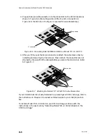
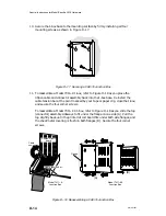
9. Remove the J-box base from your mounting surface, and then install the bottom
two wall anchors.
Summary of Contents for AViiON 5000 Series
Page 2: ......
Page 6: ......
Page 12: ...Preface x 014 001867 ...
Page 86: ...Configuring VME Option Boards 2 52 014 001867 ...
Page 144: ...Connecting External Devices to VME Option Boards 4 44 014 001867 ...
Page 150: ...VME Backplane Connector Signals and Power Distribution A 6 014 001867 ...
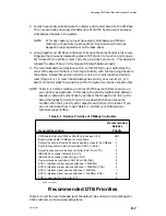
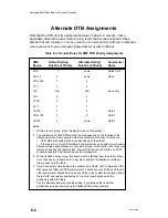
Page 196: ...Assigning VME Data Bus and Interrupt Priorities E 10 014 001867 ...
Page 206: ......
Page 210: ...Appendix Title ...


