
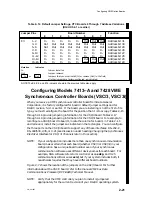

Configuring VME Option Boards
2-30
014–001867
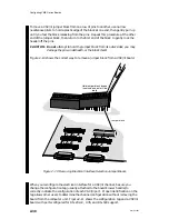
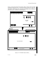
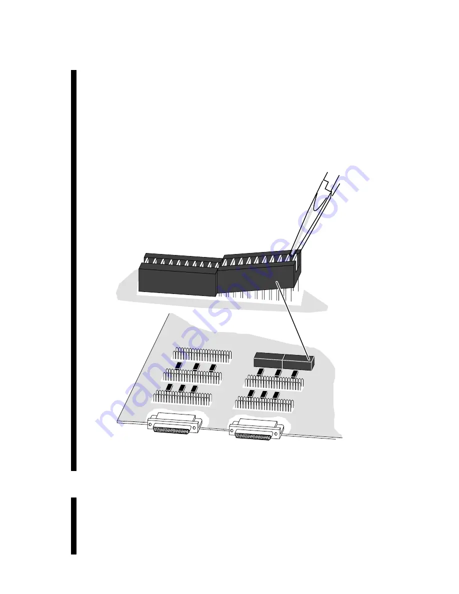
To move a VSC/3i jumper block from one row of pins to another, use narrow
needlenose pliers to hold a plastic edge of the block at one end, then gently pull up
until you feel the block releasing from the pins. Repeat this procedure at the other
end of the jumper block, then return to the first end of the block to gently rock the
header off the pins.
CAUTION: Do not attempt to hold the jumper block from its outer sides; you may
damage the pins underneath, or the block itself.
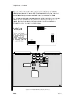
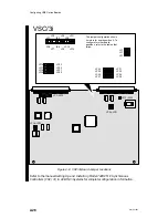
Figure 2–10 shows the correct way to remove a jumper block from a VSC/3i board.
Jumper block
Figure 2–10 Removing Electrical Interface Selection Jumper Blocks
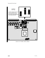
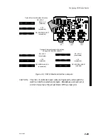
When you reconfigure the electrical interface for a VSC/3i channel, be sure you
change the configuration tag (usually attached to the board’s lower handle) to
correctly indicate the configuration of each VSC/3i port. Proper identification on the
tag allows other users to determine the channel configuration without removing the
board from the computer unit. Figure 2–11 shows the configuration tag and a VSC/3i
board with ports configured for RS–232–C, V.35, and RS–530 support.
Summary of Contents for AViiON 5000 Series
Page 2: ......
Page 6: ......
Page 12: ...Preface x 014 001867 ...
Page 86: ...Configuring VME Option Boards 2 52 014 001867 ...
Page 144: ...Connecting External Devices to VME Option Boards 4 44 014 001867 ...
Page 150: ...VME Backplane Connector Signals and Power Distribution A 6 014 001867 ...
Page 196: ...Assigning VME Data Bus and Interrupt Priorities E 10 014 001867 ...
Page 206: ......
Page 210: ...Appendix Title ...


