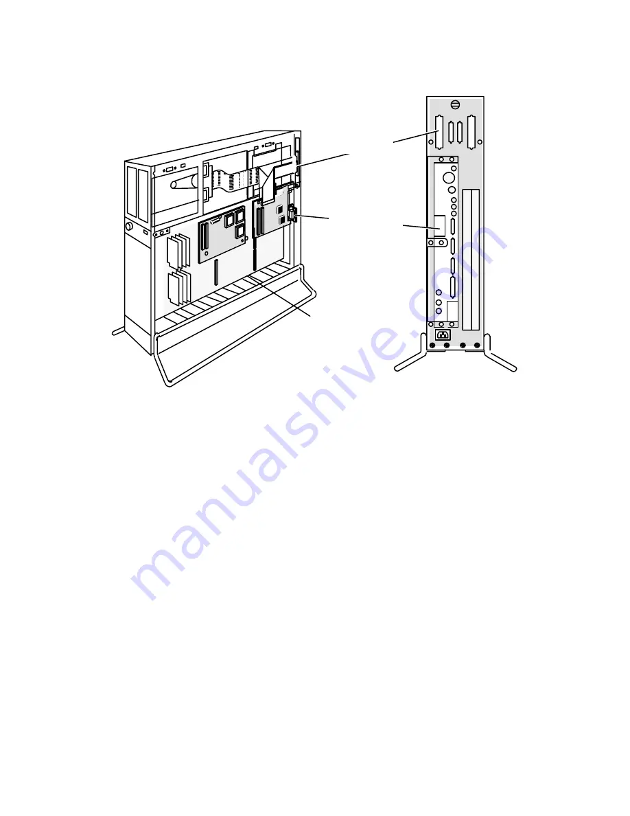
CPU, I/O Expansion, and Graphics Boards
9-9
014–002091
Computer unit
(top and right side covers removed)
System board
ÍÍÍ
ÍÍÍ
ÍÍ
ÍÍ
ÍÍ
ÍÍ
ÍÍ
ÍÍ
ÍÍ
ÍÍ
ÍÍ
Rear view
SCSI B port
Second Ethernet
LAN port
Figure 9-10 I/O Expansion Board Location and Connectors
Removing an I/O Expansion Board
Ifyour system includes an I/O expansion board, you will need to remove the board to
replace it or to replace a failed system board. Before you can remove the board, you
must prepare a worksite, remove the computer unit's right side, and attach the ESD
wrist strap as described in Chapter 6, Expanding and Maintaining Your Computer
System."
CAUTION: Unless you are properly grounded, you can discharge static electricity and
damage components in the system.
To remove an I/O expansion board, follow the steps listed next. You will need a
medium Phillips screwdriver.
1.
Disconnect any external cables attached to the SCSI B and second LAN
connectors on your computer unit bulkhead.
2.
Disconnect the ribbon cable connecting the I/O expansion board to the SCSI B
connector as shown in Figure 9Ć11.
Summary of Contents for AViiON 530 Series
Page 1: ...Customer Documentation P R O D U C T L I N E...
Page 2: ......
Page 6: ......
Page 14: ...Preface xii 014 002091...
Page 24: ...Contents xxii 014 002091...
Page 58: ...Setting Up Your Computer System 2 18 014 002091...
Page 84: ...Setting Up and Installing a SCSI Bus 4 16 014 002091...
Page 122: ...Expanding and Maintaining Your Computer System 6 18 014 002091...
Page 148: ...Adding or Replacing Memory Modules 8 8 014 002091...
Page 182: ...Replacing the System Board 10 12 014 002091...
Page 188: ...Replacing the Fan Assembly 11 6 014 002091...
Page 236: ...Using the System Control Monitor B 22 014 002091...
Page 248: ...Solving Power Up Problems C 12 014 002091...
Page 260: ...Index 12 014 002091...
Page 262: ......
Page 266: ...Appendix Title 093 xxxxxx 2 Licensed Material Property of Data General Corporation...


