Setting Up Your Computer System
014–002091
2-15
2.
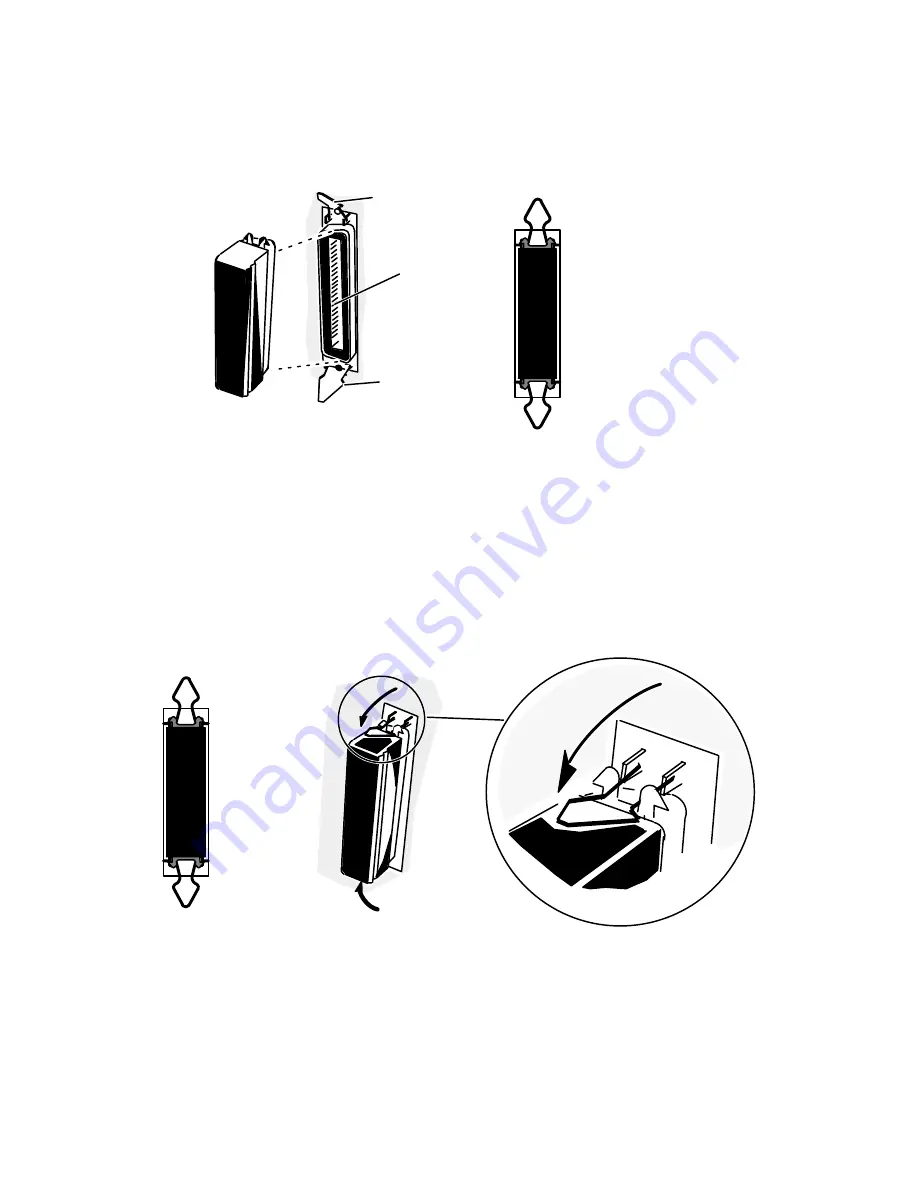
Align the connector pin numbers and the D-shaped connector bevels before
gently inserting the plug in the SCSI connector, as shown in Figure 2Ć13.
Connector pins
1–50
Plug (male)
SCSI 1 connector
(female)
Spring
clip
Bus terminator plug
inserted in rear panel
connector
(clips open)
Spring clip
Figure 2-13 Installing the SCSI Bus Terminator Plug
3.
Push the spring clips attached to the SCSI connector straight down or straight up
into the brackets on the terminator plug, as shown in Figure 2Ć14. Your vertical
pressure will push the clips into place; do not squeeze or pull the clips out of
shape.
4.
Push the spring clips attached to the SCSI 1 connector straight down or straight
up into the brackets on the terminator plug, as shown in Figure 2Ć14. Your
vertical pressure will push the clips into place; do not squeeze or pull the clips out
of shape.
Figure 2Ć14 Securing a SCSI Bus Terminator
NOTE: To remove a terminator, simply reverse the process illustrated above; pull the
clips vertically and gently pull the terminator out of the rear panel connector.
Summary of Contents for AViiON 530 Series
Page 1: ...Customer Documentation P R O D U C T L I N E...
Page 2: ......
Page 6: ......
Page 14: ...Preface xii 014 002091...
Page 24: ...Contents xxii 014 002091...
Page 58: ...Setting Up Your Computer System 2 18 014 002091...
Page 84: ...Setting Up and Installing a SCSI Bus 4 16 014 002091...
Page 122: ...Expanding and Maintaining Your Computer System 6 18 014 002091...
Page 148: ...Adding or Replacing Memory Modules 8 8 014 002091...
Page 182: ...Replacing the System Board 10 12 014 002091...
Page 188: ...Replacing the Fan Assembly 11 6 014 002091...
Page 236: ...Using the System Control Monitor B 22 014 002091...
Page 248: ...Solving Power Up Problems C 12 014 002091...
Page 260: ...Index 12 014 002091...
Page 262: ......
Page 266: ...Appendix Title 093 xxxxxx 2 Licensed Material Property of Data General Corporation...


