Removing memory modules
6-5
014–002250–01
Removing memory modules
Before you can remove any memory modules, you must remove the
computer unit cover and attach the ESD wrist strap as described in
the “Opening the Computer Unit” section of Chapter 4.
CAUTION:
Unless you are properly grounded, you can discharge static
electricity and damage components in the system.
"
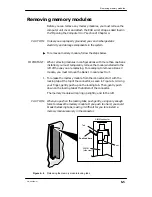
To remove a memory module, follow the steps below.
IMPORTANT:
When removing modules in configurations with more than one bank
installed, you must temporarily remove the module installed to the
left of the one you are replacing. For example, to remove a Bank 0
module, you must remove the Bank 1 module next to it.
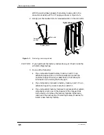
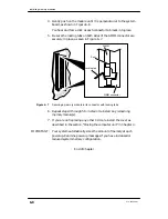
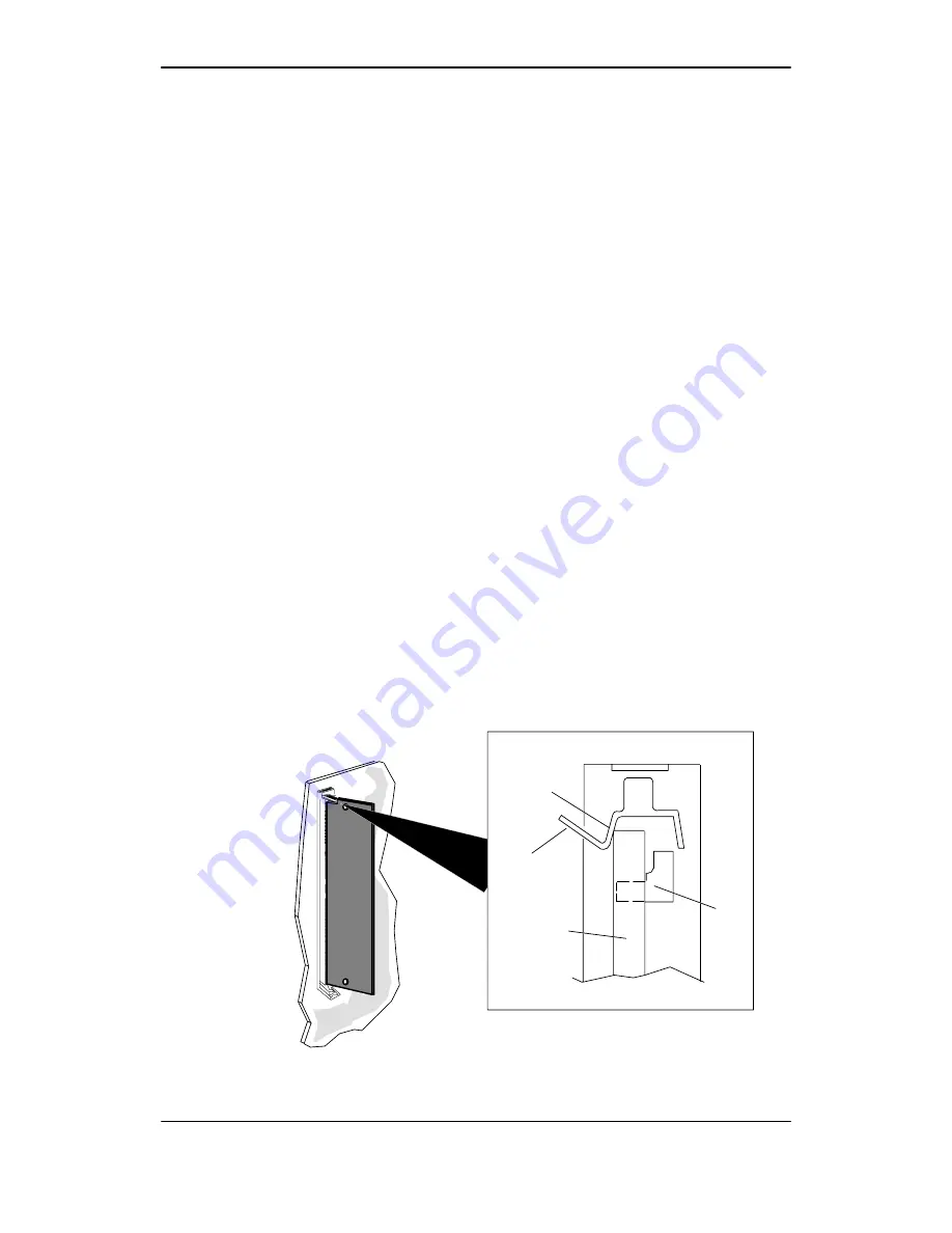
1. To release the memory module from the connector, start with the
locking tab at the top of the connector, as seen in Figure 6–4. Using
your finger, gently push up on the locking tab. Then, gently push
down on the locking tab at the bottom of the connector.
The memory module will spring up slightly, and to the left.
CAUTION:
When you push on the locking tabs, push gently, using only enough
force to release the memory module. If you push too hard, you could
break the locking tabs, making it difficult for you to reinstall a
memory module securely in the connector.
SIMM
(side view)
SIMM connector
Post
Push tab here
Tab
Figure 6–4
Releasing the memory module locking tabs
Summary of Contents for AViiON 550 Series
Page 2: ......
Page 6: ......
Page 12: ...Joining our users group x 014 002250 01 ...
Page 86: ...Opening and closing the computer unit 4 12 014 002250 01 ...
Page 96: ...Installing a drive assembly 5 10 014 002250 01 ...
Page 188: ......
Page 191: ......


