Installing memory modules
6-7
014–002250–01
Installing memory modules
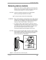
Before you can install any memory modules, you must remove the
computer unit cover and attach the ESD wrist strap as described in
Chapter 4, “Expanding and maintaining your computer.”
When installing add–on memory modules begin by installing the
memory module in the lowest numbered open bank. Figure 6–2
(earlier in this chapter) shows the numbering scheme for the
memory module connectors. Table 6–2 lists valid configurations.
"
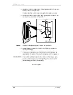
To install a memory module, use the following steps.
1. Carefully remove the memory module from its package. Save the
antistatic shipping bag and packing materials in case you need to
return the module.
CAUTION:
If you need to set the memory module down, put it back inside the
antistatic shipping bag.
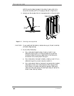
2. If you are installing a memory modules in Banks 0 or 1, you must
first temporarily remove any modules installed to the left (Bank 1
or Bank 2), as described in the previous section.
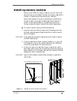
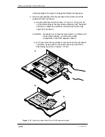
3. As shown in Figure 6–6, align the memory module so its notch is
facing down (towarrd the lower locking tab). Position the module at
approximately a 20
°
to 30
°
angle; then press the module’s connector
edges gently into the connector post.
CAUTION:
Never force the memory module into the connector or against the
locking tabs.
Memory
module
ÉÉÉÉÉÉÉÉÉ
ÉÉÉÉÉÉÉÉÉ
Connector
Insert module into connector at an angle,
then push left to lock in place.
System board
Figure 6–6
Inserting the memory module in the connector
Summary of Contents for AViiON 550 Series
Page 2: ......
Page 6: ......
Page 12: ...Joining our users group x 014 002250 01 ...
Page 86: ...Opening and closing the computer unit 4 12 014 002250 01 ...
Page 96: ...Installing a drive assembly 5 10 014 002250 01 ...
Page 188: ......
Page 191: ......


