Adding or replacing a graphics controller (550 series)
7-20
014–002250–01
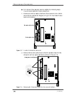
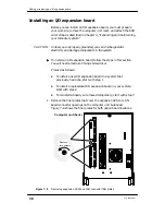
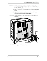
2. Carefully remove the graphics controller from its package. Save the
antistatic shipping bag and packing materials to use if you have to
return the board.
CAUTION: If you need to set the board down, put it back inside the
antistatic shipping bag.
IMPORTANT:
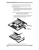
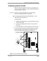
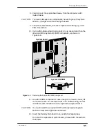
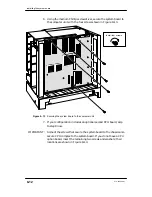
For steps 3 through 5: refer to Figure 7–20 if you have an 8–bit
controller (the standard configuration); refer to Figure 7–21 if you
have a 24–bit controller.
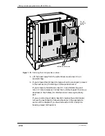
3. Position the graphics board so that its external I/O connectors fit
inside the lower slot opening in the computer unit bulkhead.
4. Align the interboard connectors on the system board and on the
graphics board. Press the interboard connectors together to create a
firm connection.
If you cannot press the connectors together easily, make sure that
the connectors are aligned correctly; then, try pressing them
together again.
5. Secure the graphics board to the system board with screws, as
shown in Figure 7–20 or Figure 7–21.
ÉÉÉ
ÉÉÉ
ÉÉÉ
ÉÉÉ
ÉÉÉ
ÉÉÉ
ÉÉÉ
ÉÉÉ
ÉÉÉ
ÉÉÉ
ÉÉÉ
ÉÉÉ
ÉÉÉ
ÉÉÉ
Interboard connectors
Figure 7–20 Installing the 8–bit graphics controller
Summary of Contents for AViiON 550 Series
Page 2: ......
Page 6: ......
Page 12: ...Joining our users group x 014 002250 01 ...
Page 86: ...Opening and closing the computer unit 4 12 014 002250 01 ...
Page 96: ...Installing a drive assembly 5 10 014 002250 01 ...
Page 188: ......
Page 191: ......

