Preparing a replacement system board
8-6
014–002250–01
Preparing a replacement system board
Before you can install the new system board, you need to prepare
your work site, remove the computer unit cover, and attach the ESD
wrist strap as described in Chapter 4.
Then, prepare the new system board for installation as described in
this section.
"
First, install the original PROM component (the component you
removed from the failed system board) on the replacement system
board as described below.
CAUTION:
You must install the original PROM on the replacement system
board to access some applications software.
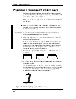
1. Start with step 2 if the replacement system board does not have a
PROM component installed.
If the replacement system board has a PROM component already
installed, remove that component from the replacement system
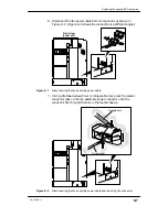
board. Using a flat–blade screwdriver, gently pry up one end and
then the other end of the component until it is loose enough to
remove by hand (as shown in Figure 8–6).
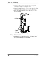
2. Examine the original PROM component to see if its connector pins
are straight.
Angled pin
Spread pins
Straight pins
3. If the pins are spread too far apart or angled incorrectly, straighten
the pins as follows.
Lay the PROM component down on one side on an ESD–free table,
and carefully roll the component to bend the pins into line as shown
in Figure 8–7. Once the pins are in line on one side, repeat this
procedure with the other side of the component.
ÉÉÉÉÉÉ
ÉÉÉÉÉÉ
Figure 8–7
Straightening the pins on the PROM component
Summary of Contents for AViiON 550 Series
Page 2: ......
Page 6: ......
Page 12: ...Joining our users group x 014 002250 01 ...
Page 86: ...Opening and closing the computer unit 4 12 014 002250 01 ...
Page 96: ...Installing a drive assembly 5 10 014 002250 01 ...
Page 188: ......
Page 191: ......


