Integrated I/O connectors and signals
A-7
014–002250–01
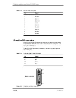
Parallel port connector
The I/O cable from a parallel printer connects to the system board
port through a 25–pin, female D–connector (DB25) located on the
back of the computer system.
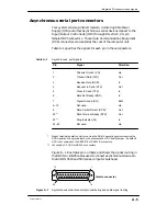
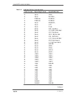
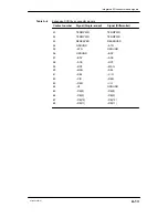
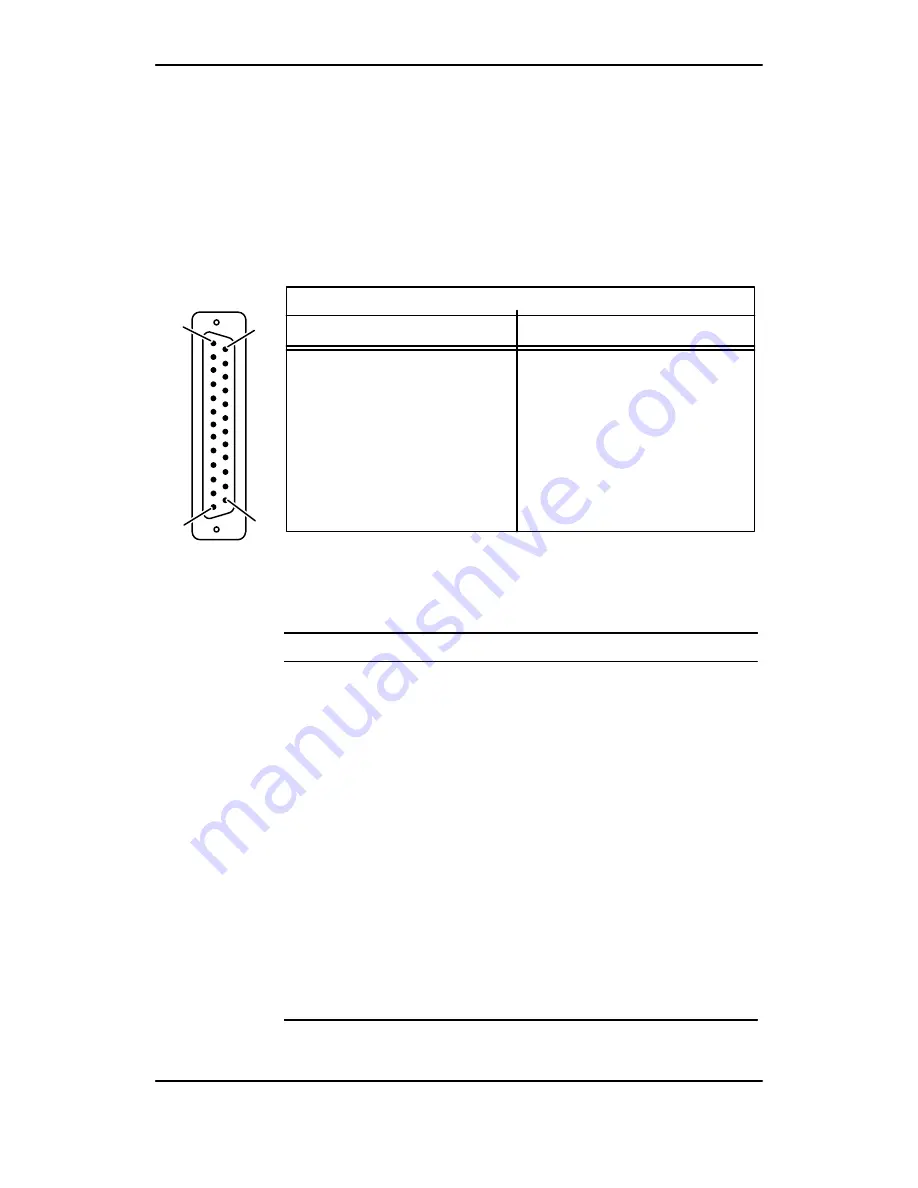
Table A–3 lists the signals and pin numbers for the parallel printer
connector; Figure A–3 illustrates the pin numbering and shows the
25– to 36–pin conversion accomplished by the parallel printer cable.
DB25
Connector
CHAMP-36
Connector
to
Parallel Printer Cable Signal Pins
DB25
Connector
CHAMP-36
Connector
to
14
13
1
25
female connector
Figure A–3
Printer connector pin numbering and cable signal routing
Table A–3
Parallel printer connector pin signals
Pin
Signal
1
– Strobe
2
+ Data 0
3
+ Data 1
4
+ Data 2
5
+ Data 3
6
+ Data 4
7
+ Data 5
8
+ Data 6
9
+ Data 7
10
– Acknowledge
11
+ Busy
12
+ Paper End (out of paper)
13
+ Select (on line)
Continued
Summary of Contents for AViiON 550 Series
Page 2: ......
Page 6: ......
Page 12: ...Joining our users group x 014 002250 01 ...
Page 86: ...Opening and closing the computer unit 4 12 014 002250 01 ...
Page 96: ...Installing a drive assembly 5 10 014 002250 01 ...
Page 188: ......
Page 191: ......


